Electromagnetic Field Pickup for Musical Instruments

a pickup and electromagnetic field technology, applied in the field of music, can solve the problems of reducing the resulting frequency response, poor low frequency response, subject to external noise and frequency response limitation, etc., and achieve the effects of enhancing the quality of the recording, reducing the development and manufacturing cost, and accurate reproduction

Inactive Publication Date: 2009-09-10
LOFTUS ROBERT FRANCIS JOSEPH
View PDF15 Cites 16 Cited by
  • Summary
  • Abstract
  • Description
  • Claims
  • Application Information

AI Technical Summary

Benefits of technology

[0029]a) accurate reproduction of a full frequency range of sound emitted by of an instrument;
[0030]b) preservation of relative amplitude and duration of each frequency;
[0031]c) use of conventional electrical components in combination resulting in reduced development and manufacturing costs;
[0032]d) enhancement of quality of a recording and reproduction of music from an instrument;
[0033]e) simplification of pickup construction resulting in increased flexibility and improvement in the instrument's aesthetic appearance;
[0034]f) reduced size allowing greater application flexibility and easier retro fitting to the instrument;

Problems solved by technology

Specific Problems with Background Art Including:
a) magnetic pickup needs steel strings to vibrate in a magnetic field with a large inductive coil to pick up audio frequency vibrations consequently loading a vibrating string and reducing a resulting frequency response;
b) a piezoelectric pickup needs a vibrating component including at least one of a bridge and a soundboard, often leading to a poor low frequency response;
c) an acoustic microphone relies upon variations in air pressure to transfer a musical vibration and is subject to an external noise and frequency response limitation;
d) an optical pickup requires a light source and detector to be above and below each of an instrument's strings without affecting operation of an instrument, the optical pickup is receptive to displacement of a string's shadow in one dimension only, and accordingly, information pertaining to sound received by an optical pickup is limited as a string vibrates in three dimensions, as a result sound reproduction is limited in quality and physical requirements limit the optical pickup's application to a bridge area of the instrument.

Method used


Image

  • Electromagnetic Field Pickup for Musical Instruments
  • Electromagnetic Field Pickup for Musical Instruments
  • Electromagnetic Field Pickup for Musical Instruments

Examples


Embodiment Construction

[0073]Best Mode

[0074]Definitions and Terms

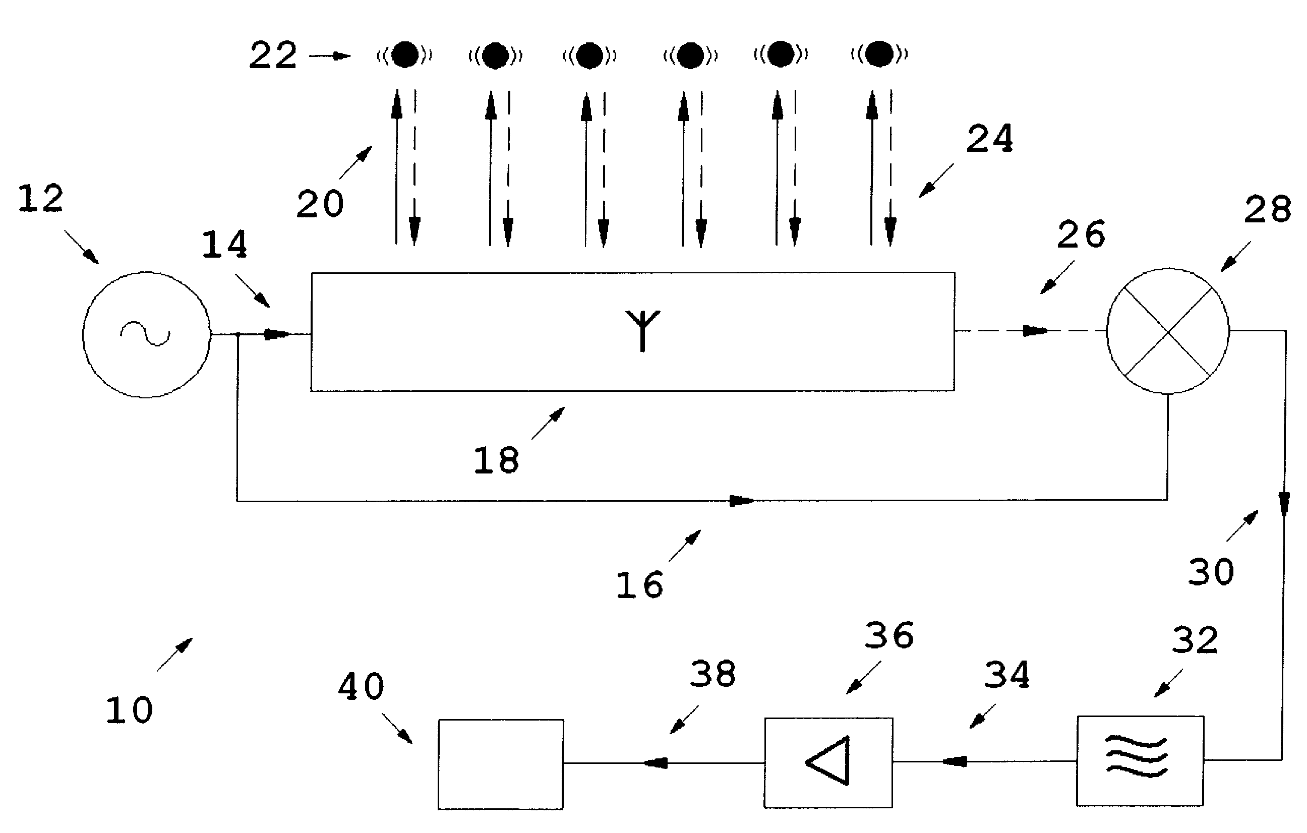
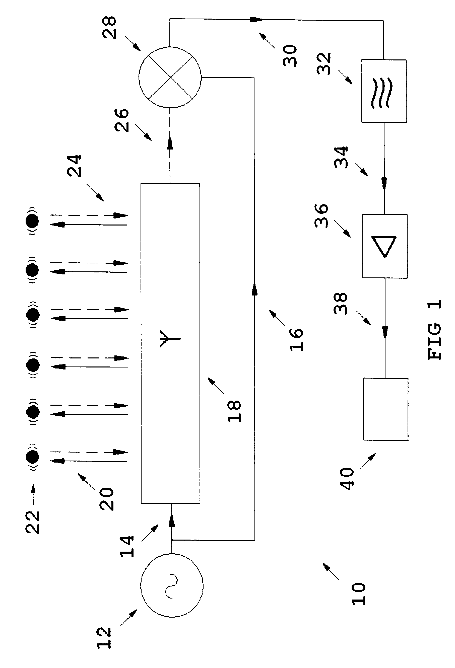
[0075]“Detection”, also called demodulation, is a process of re-creating original modulating frequencies (intelligence) from frequencies which are present in a composite signal”, extracted and adapted from Basic Electronics, Prepared by Bureau of Naval Personnel, Dover, first published 1973, at p 232.

[0076]Consistent with the definition of “detection” as recited above, a term “mixer” can further comprise filtration.

[0077]Modulation—“Radio—in radio transmission, the process whereby the frequency, amplitude, or some other property of a carrier wave (signal-carrying wave) is made to increase or decrease instantaneously in response to variations in the characteristics of the signal being transmitted”—Chambers Concise Dictionary & Thesaurus, Chambers Harrap Publishers, Edinburgh, 2001.

[0078]A transducer is “A device that converts one form of energy into another. Electronic transducers either convert electric energy to another form of energy or co...


PUM


Abstract

An electromagnetic field pickup (10) for a musical instrument including an electromagnetic signal generator (12), an electromagnetic field transducer (18), a mixer (28), the electromagnetic signal generator (12), the electromagnetic field transducer (18) and the mixer (28) are respectively connected in series, the electromagnetic signal generator (12) is also connected directly to the mixer (28), so constructed and arranged that when power is supplied to the electromagnetic field pickup (10) an audio electrical signal of substantially same pitch, intonation and sustain as a vibrating element (22) of the instrument is generated.

Description

CROSS-REFERENCE TO RELATED APPLICATIONS [0001]The present invention claims benefit of priority to U.S. patent application Ser. No. 61 / 038,567, filed on Mar. 21, 2008 and Australia patent application serial number 2008901054, filed on Mar. 4, 2008; the contents of each are herein incorporated by reference.BACKGROUND OF INVENTION [0002]1. Technical Field[0003]The present invention has application to the field of music and to the sub fields of electrical musical tone generation using transducers and electromagnetic fields and with particular application to stringed and percussion instruments.[0004]2. Background Art[0005]Since Thomas Edison first used a vibrating thorn to cut a sound track in a revolving wax cylinder producing a very rough and poor quality sound by contemporary standards, many scientists, inventors and experimenters have striven for perfect reproduction and recording of sound and music, using devices referred to as “pickups” to detect and attempt to reproduce sound prod...

Claims


Application Information

Patent Timeline
Patent Type & Authority Applications(United States)
IPC IPC(8): G10H3/18
CPCG10H3/18G10H2220/565G10H2220/431
Inventor LOFTUS, ROBERT FRANCIS JOSEPH
Owner LOFTUS ROBERT FRANCIS JOSEPH
Why Eureka
Try Eureka