
Dual Sided Photovoltaic Package

a photovoltaic package and double-sided technology, applied in the field of solar power generation, can solve the problems of double-sided cells having a low power density, large mass, and impact with other components, and achieve the effects of optimizing power generation, flexible structure, and optimizing weigh

Inactive Publication Date: 2009-09-10
EMCORE SOLAR POWER
View PDF25 Cites 62 Cited by
  • Summary
  • Abstract
  • Description
  • Claims
  • Application Information

AI Technical Summary

Benefits of technology

[0012]It is a primary advantage of the present invention that the double sided photovoltaic package is capable of converting solar radiation incident on both incident and reflective photovoltaic cells and thereby, optimizes power generation and optimizes weight. Another advantage of the present invention is that it has a flexible structure.
[0013]It is preferable that the reflective photovoltaic cell is located on an opposite side to the incident photovoltaic cell. Additionally it is preferable that the structure of the incident photovoltaic cell is optimized for converting non-reflected solar light to electrical energy and wherein the structure of the reflected photovoltaic cell is optimized for converting reflected solar light to electrical energy.
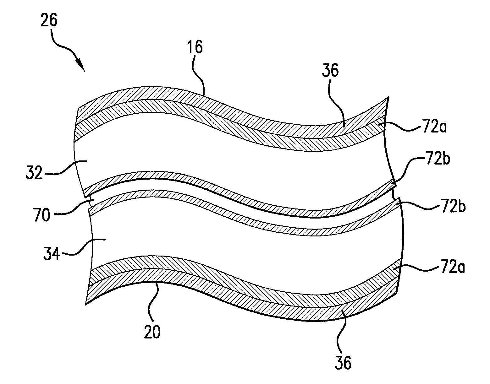
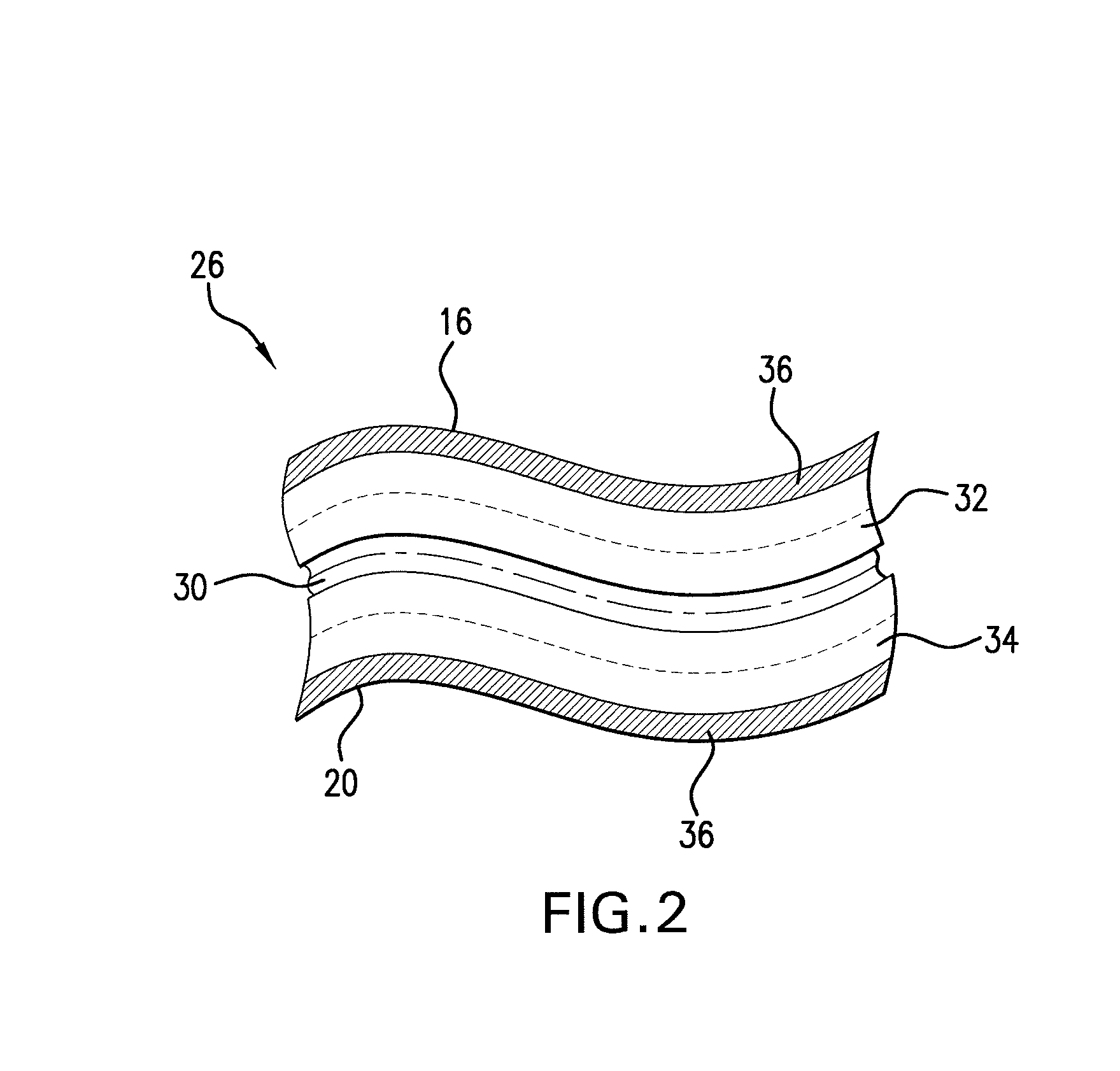
[0014]It is preferable that a conductive adhesive is sandwiched between the incident photovoltaic cell and the reflective photovoltaic cell to provide a common ground to both photovoltaic cells. Furthermore, it is preferable that the absorbing surfaces of the incident and reflective photovoltaic cells are coated with a flexible transparent membrane.
[0015]It is preferable that the incident photovoltaic cell and the reflective photovoltaic cell are each sandwiched between a front metal contact and a back metal contact so that each absorbing surface abuts a corresponding front metal contact. Additionally, it is preferable that a flexible dielectric adhesive is sandwiched between the incident photovoltaic cell and the reflective photovoltaic cell, and the flexible dielectric adhesive abuts the back metal contact of the incident photovoltaic cell and the reflective photovoltaic cell. Finally, it is preferable that the front metal contact of both the incident photovoltaic cell and the reflective photovoltaic cell is coated with a flexible transparent membrane.
[0016]In different embodiments the incident and the reflective photovoltaic cells are optionally three junction, four junction or five junction photovoltaic cells.
[0017]In an embodiment, a plurality of double-sided photovoltaic packages according to the present invention are combined to form an array. In another embodiment, the double-sided photovoltaic packages are arranged in a string formation wherein at least one cell is interconnected to two adjacent cells. In a another embodiment the incident photovoltaic cell of at least one double-sided package is interconnected to an incident photovoltaic cell of each adjacent double-sided package and the reflective photovoltaic cell of the at least one double-sided package is interconnected to the reflective photovoltaic cell of each adjacent double-sided package. In a further embodiment, the array is mounted on a transparent panel.

Problems solved by technology

These two requirements are often in conflict because, generally, the more power a photovoltaic cell (or array of cells) is capable of producing the larger the cell (or array of cells) is and, therefore, the greater its mass.
For example, the launch process creates many strong vibrations and causes photovoltaic cells to rub against, and impact with, other components.
Unfortunately, however, known double-sided cells often have a low power density and are too rigid for space applications.

Method used


Image

  • Dual Sided Photovoltaic Package
  • Dual Sided Photovoltaic Package
  • Dual Sided Photovoltaic Package

Examples


Embodiment Construction

[0029]A preferred embodiment of the invention will now be described in detail with reference to the accompanying drawings, wherein like reference numerals relate to like components.

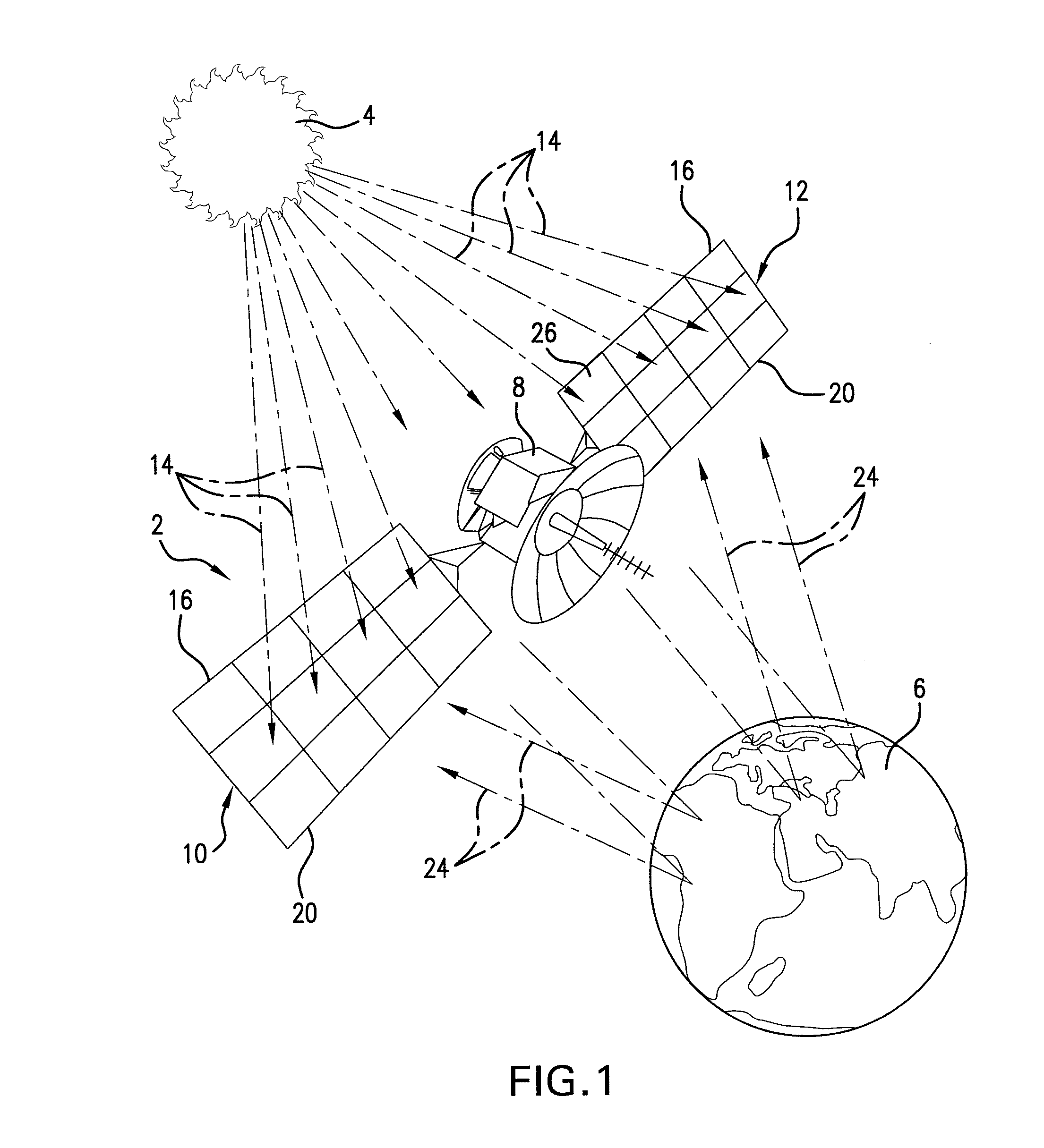
[0030]FIG. 1 depicts a typical environment in which an embodiment of the present invention is intended to operate. A satellite 2 is located in-between the Sun 4 and the Earth 6. The satellite 2 comprises a control unit 8 and two photovoltaic arrays 10 and 12. The control unit 8 is responsible for controlling the functionality of the satellite 2 and, although it is required for the satellite to operate, it does not form part of the present invention and, therefore, the control unit 8 will not be discussed in detail.

[0031]The satellite 2 is positioned and arranged so that direct solar radiation 14 from the Sun 4 is incident on a top surface 16 of photovoltaic arrays 10 and 12. Furthermore, a bottom surface 20 of photovoltaic arrays 10 and 12 have incident upon them indirect solar radiation 24 from the Sun 4...


PUM


Abstract

A double-sided photovoltaic package with an incident photovoltaic cell and a reflective photovoltaic cell. Both photovoltaic cells have a corresponding absorbing surface for absorbing solar radiation. The incident photovoltaic cell and the reflective photovoltaic cell are arranged so that when the absorbing surface of the incident photovoltaic cell is located to receive incident non-reflected solar radiation the absorbing surface of the reflective photovoltaic cell is located to receive reflected solar radiation. The structure of the incident photovoltaic cell is adapted to convert non-reflected light to electrical energy and the structure of the reflective photovoltaic cell is adapted to convert reflected light to electrical energy. Additionally, in the preferred embodiment, the incident photovoltaic cell and the reflective photovoltaic cell both comprise inverted metamorphic multijunction photovoltaic cells. Furthermore, a plurality of double-sided photovoltaic packages according to the present invention may be interconnected in a string formation and mounted on a transparent panel to form an array.

Description

TECHNICAL FIELD[0001]The present invention relates to solar power generation. More specifically, the present invention provides a new photovoltaic package with a high power output per unit area and a flexible structure that is suitable for space applications.BACKGROUND OF THE INVENTION[0002]It is known to produce photovoltaic cells for space applications in order to provide electric power for devices, such as, for example, a satellite. It is also known to optimize known photovoltaic cells to absorb solar radiation over a certain portion of the electromagnetic spectrum. An optimized photovoltaic cell converts incident solar radiation with the target portion of the electromagnetic spectrum into electricity with improved efficiency. Accordingly, it is known to optimize photovoltaic cells to absorb the specific spectrum of solar radiation emitted directly from the Sun. The process of optimization involves selecting the material composition and construction of the photovoltaic cell accor...

Claims


Application Information

Patent Timeline
IPC IPC(8): H01L31/052H01L31/06
CPCB64G1/443H01L31/03046H01L31/035281Y02E10/544H01L31/06875Y02E10/52H01L31/042H01L31/0504H01L31/043
Inventor SHARPS, PAUL R.
Owner EMCORE SOLAR POWER
Learn More