Cordless Roller Shade

Inactive Publication Date: 2009-09-10
CHENG LI MING
View PDF0 Cites 30 Cited by
  • Summary
  • Abstract
  • Description
  • Claims
  • Application Information

AI Technical Summary

Benefits of technology

[0003]The present invention aims to provide a cordless roller shade to resolve the aforesaid problem of the conventional window coverings that cannot be anchored at a selected elevation during retraction

Problems solved by technology

The winding buffer means 11 thus constructed has drawbacks, notably the window coverings can on

Method used


Image

  • Cordless Roller Shade
  • Cordless Roller Shade
  • Cordless Roller Shade

Examples


Embodiment Construction

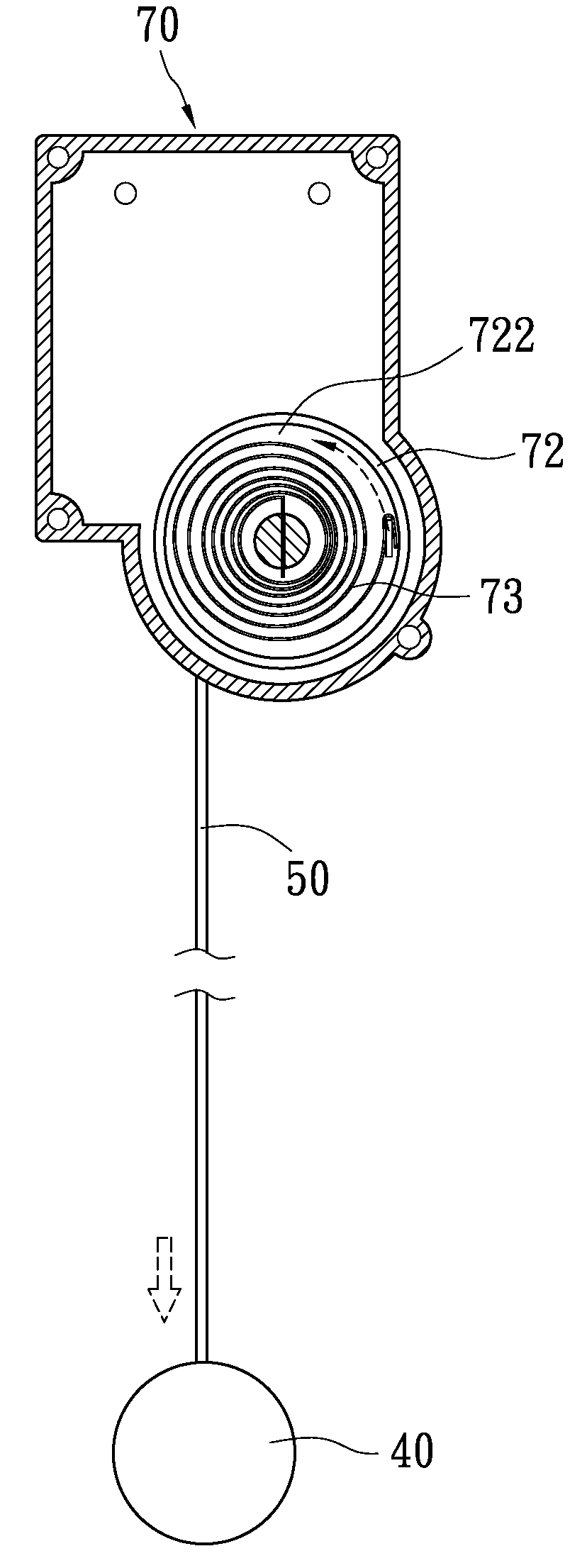
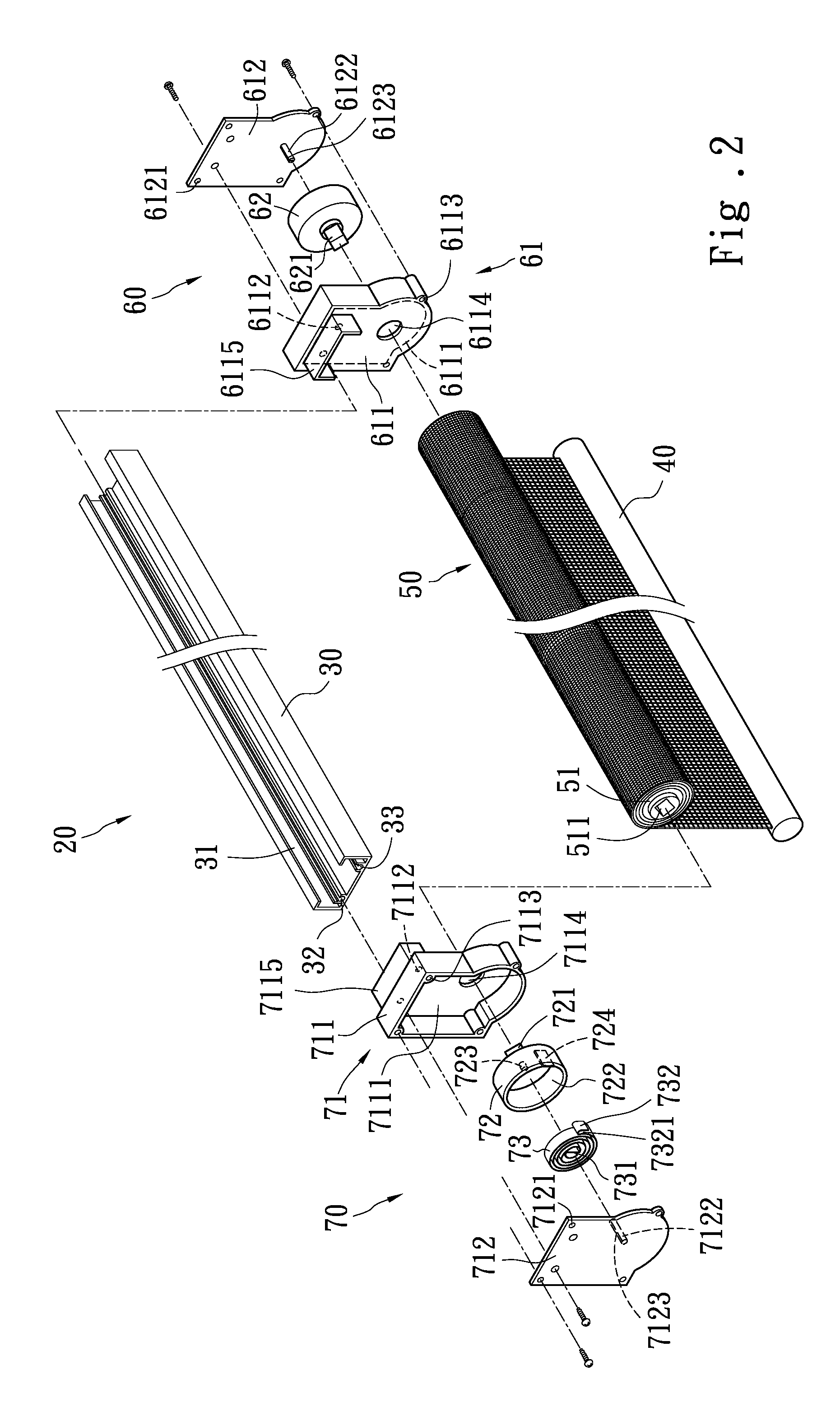
[0017]Please refer to FIG. 2, the cordless roller shade 20 according to the invention has an upper elongated support 30 with an anchor seat 60 located at one end and an automatic winding means 70 at another end to form a linking relationship to do transmission and control retraction and extension of the cordless roller shade 20. The cordless roller shade 20 mainly includes the upper elongated support 30, a lower elongated support 40, a shade assembly 50, the anchor seat 60 and the automatic winding means 70.

[0018]The upper elongated support 30 is elongate and has a guiding trough 31 inside that has two ends formed respectively a fastening trough 32 and 33.

[0019]The lower elongated support 40 is elongate and spaced from the upper elongated support 30 at a lower side.

[0020]The shade assembly 50 is located between the upper elongated support 30 and the lower elongated support 40. In an embodiment shown in the drawings, it has an axle 51 with an axle hole 511 formed at one end thereof.

[...


PUM


Abstract

A cordless roller shade includes at least an upper elongate support, a lower elongate support, an anchor seat and an automatic winding means. The anchor seat and the automatic winding means are installed on two end of the upper elongate support. A shade assembly also is provided that has an axle at one side coupling with the anchor seat and rotatable. The automatic winding means has a second cap assembly hinged a second cap inside that has a second shaft on another side. The second cap holds a wound elastic element inside. The second shaft is coupled with the axle of the shade assembly. Through rotation of the second cap the cordless roller shade can be retracted and extended easily and smoothly.

Description

FIELD OF THE INVENTION[0001]The present invention relates to a cordless roller shade and particularly to a shade that has an automatic winding means and an anchor seat that are coupled together to automatically control retraction and extension of the cordless roller shade to facilitate operation.BACKGROUND OF THE INVENTION[0002]There are many different types of window coverings on the market such as Venetian blinds, pleated window coverings, roman shades and the like. They mainly aim to be installed at doors and windows of houses to block sunshine and serve decorative purpose. Depending on different user requirements some window coverings have a lift cord to control retraction and extension for lifting or lowering. For a single panel window coverings 10 a winding buffer means 11 is usually adopted. The winding buffer means 11 mainly includes a case, a sleeve, an external coupling member, a lid and a rotary element. To extend the shade, winding is made clockwise and the sleeve rotate...

Claims


Application Information

Patent Timeline
IPC IPC(8): A47G5/02
CPCE06B9/42
Inventor CHENG, LI-MING
Owner CHENG LI MING
Why Eureka
Try Eureka