
Shock Absorber
a technology of shock absorber and shock absorber, which is applied in the direction of shock absorber, vibration damper, spring/damper, etc., can solve the problems of deformation of the carrying table, loud noise, and broken components or counterparts, and achieve the effect of reducing the impa
- Summary
- Abstract
- Description
- Claims
- Application Information
AI Technical Summary
Benefits of technology
Problems solved by technology
Method used
Image

Examples
example
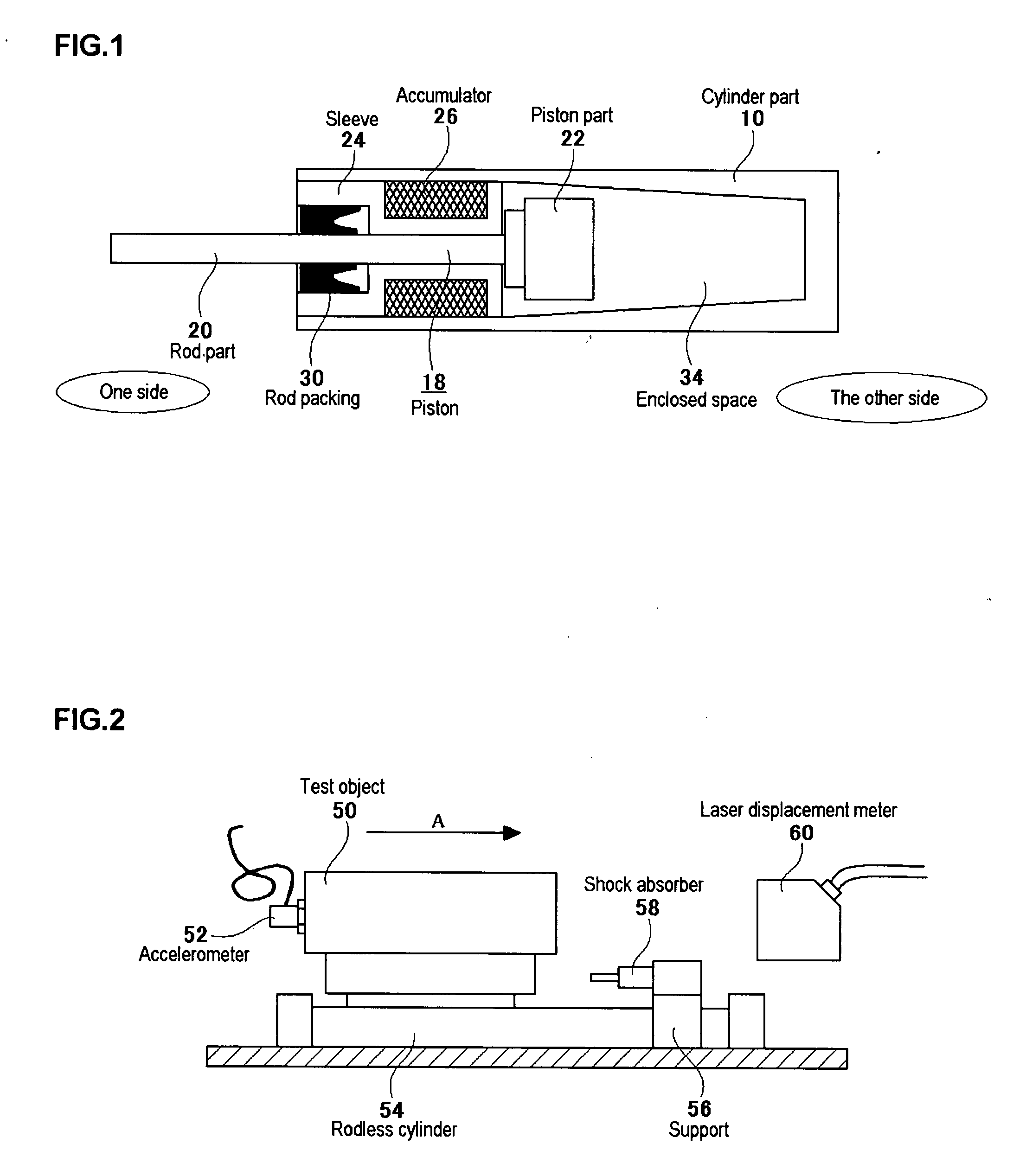
[0055]An experimental device as shown in FIG. 2 was prepared. Here, a 2.0 kg block shaped test object is indicated by 50, and an accelerometer 52 is placed at the back of the test object 50. The test object 50 together with the accelerometer 52 is mounted on a rodless cylinder 54 and can be horizontally transferred to the direction indicated by an arrow. A shock absorber 58 supported by a support 56 is placed right in front of the carrying direction of the test object 50. A laser displacement meter 60 is also placed right in front of the test object 50 towards the carrying direction allowing to measure the traveling speed of the test object 50.
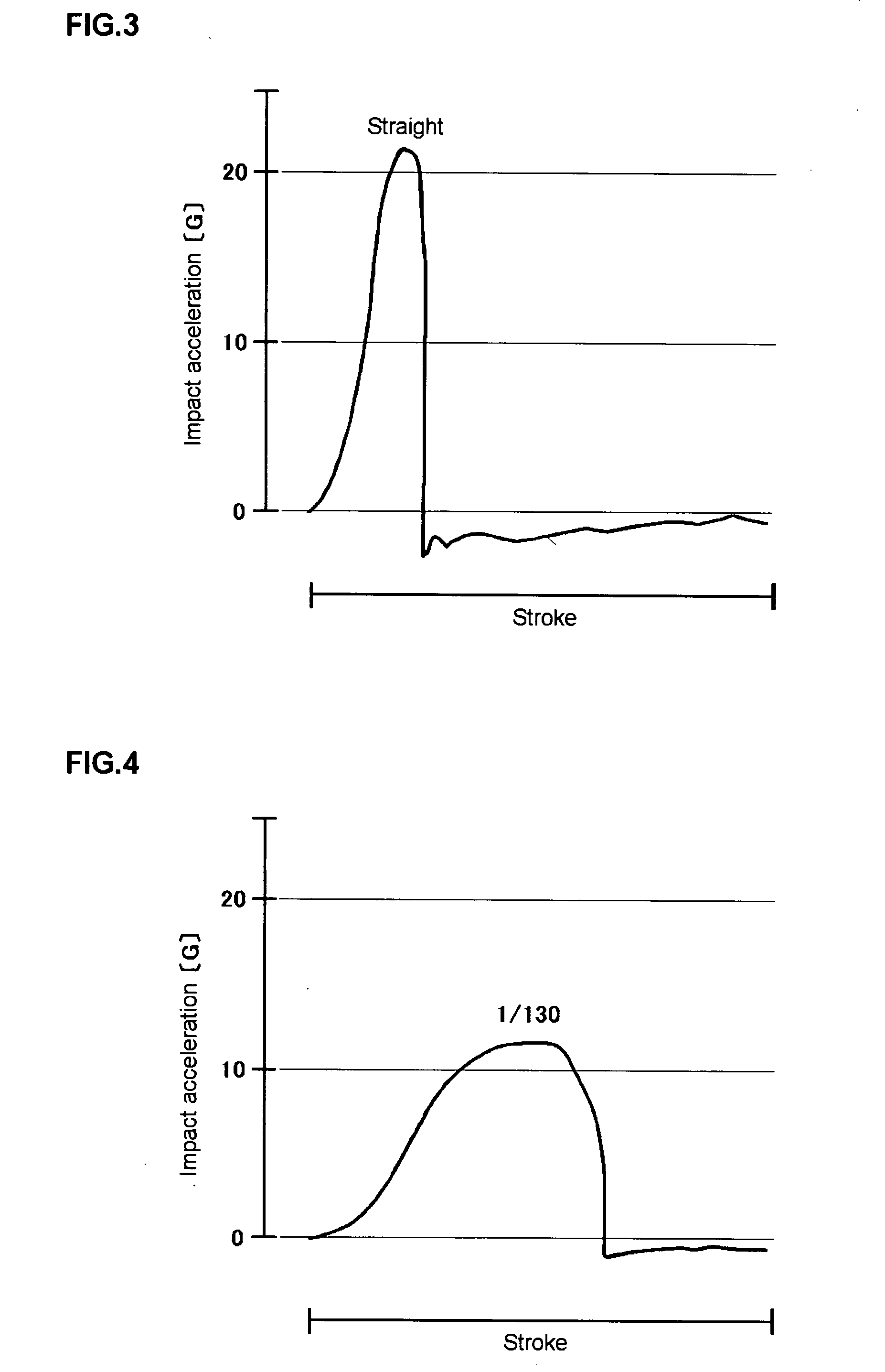
[0056]This experimental device was used to transfer the test object 50 in the direction indicated by arrow A with the air pressure inside the cylinder of the rodless cylinder 54 of 0.5 MPa, and the test object was collided at the speed of 1.0 m / s into a shock absorber with various rates of taper ranging from straight to 1 / 30 on the inner surfa...
PUM
 Abstract
Description
Claims
Application Information