Charging apparatus

a charging apparatus and charging technology, applied in the direction of electrical apparatus construction details, inductances, transportation and packaging, etc., can solve the problems of charging apparatus described above not taking into account a case in which a plurality of devices may possibly be used, and the charging operation may possibly be started, so as to achieve the effect of suppressing heat generation

Active Publication Date: 2009-09-10
CANON KK
View PDF13 Cites 226 Cited by
  • Summary
  • Abstract
  • Description
  • Claims
  • Application Information

AI Technical Summary

Benefits of technology

[0007]The present invention addresses such problems as described above, and provides a charging apparatus that can suppress heat generation even when a non-chargeable device or a foreign object is placed together with a chargeable device on the charging apparatus.

Problems solved by technology

In these charging apparatuses, when a foreign object such as a piece of metal (for example, a coin) is placed within the magnetic field generated by the primary coil, an eddy-current flowing in the piece of metal may cause heat to be generated due to the internal resistance of the piece of metal.
However, the charging apparatus described above does not take into consideration a case in which a plurality of devices are being charged in parallel.
Hence, when a chargeable device and a non-chargeable device are placed on the charging apparatus at the same time, for example, there remains a problem in which a charging operation may possibly be started despite the presence of a non-chargeable device on the charging apparatus, causing the non-chargeable device to generate heat.

Method used


Image

  • Charging apparatus
  • Charging apparatus
  • Charging apparatus

Examples


Embodiment Construction

[0016]Embodiments of the present invention will be described in detail with reference to the attached drawings. A charging apparatus that can charge a plurality of devices will be described. Note that DC means direct current and AC means alternating current, hereinafter.

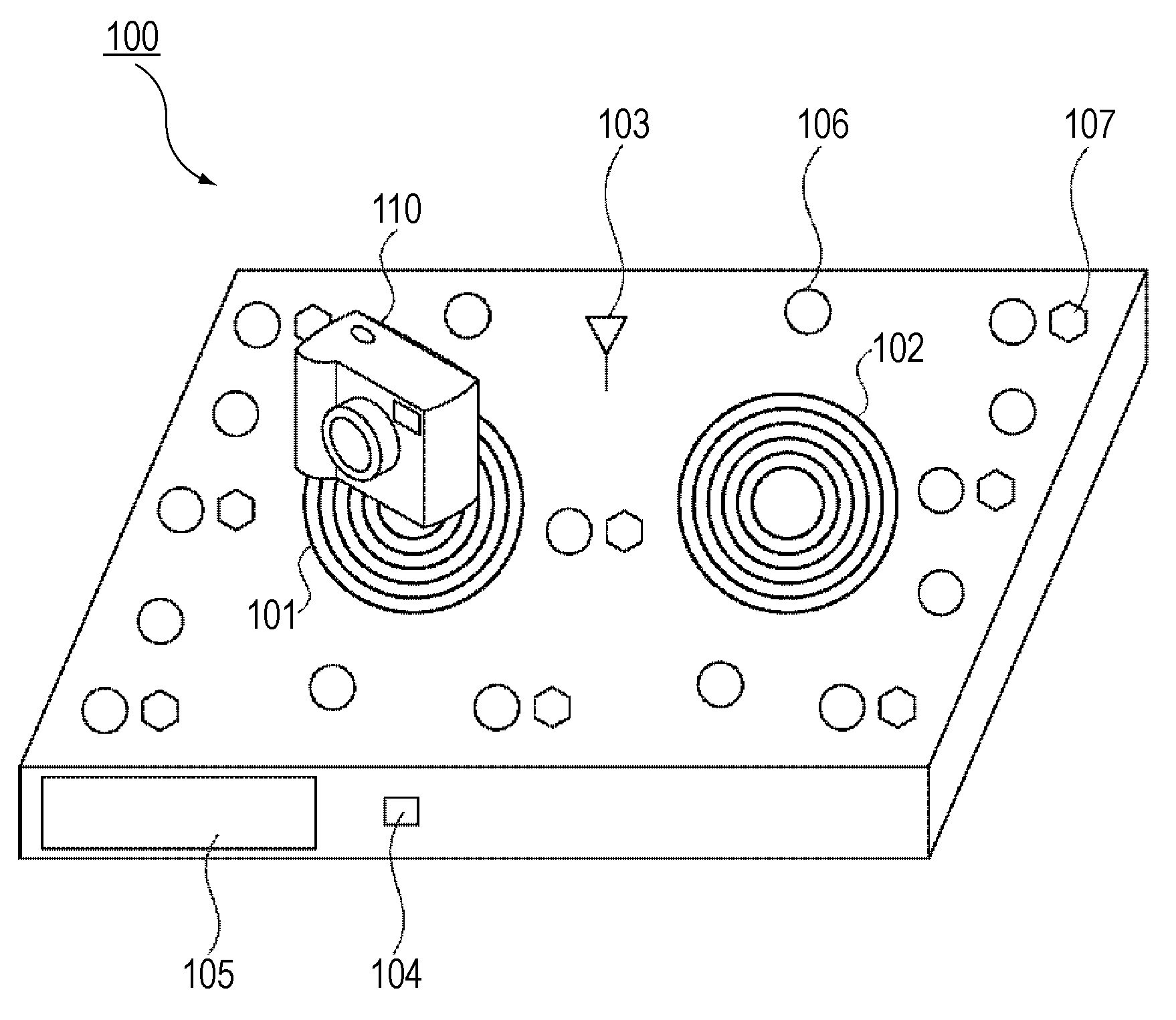
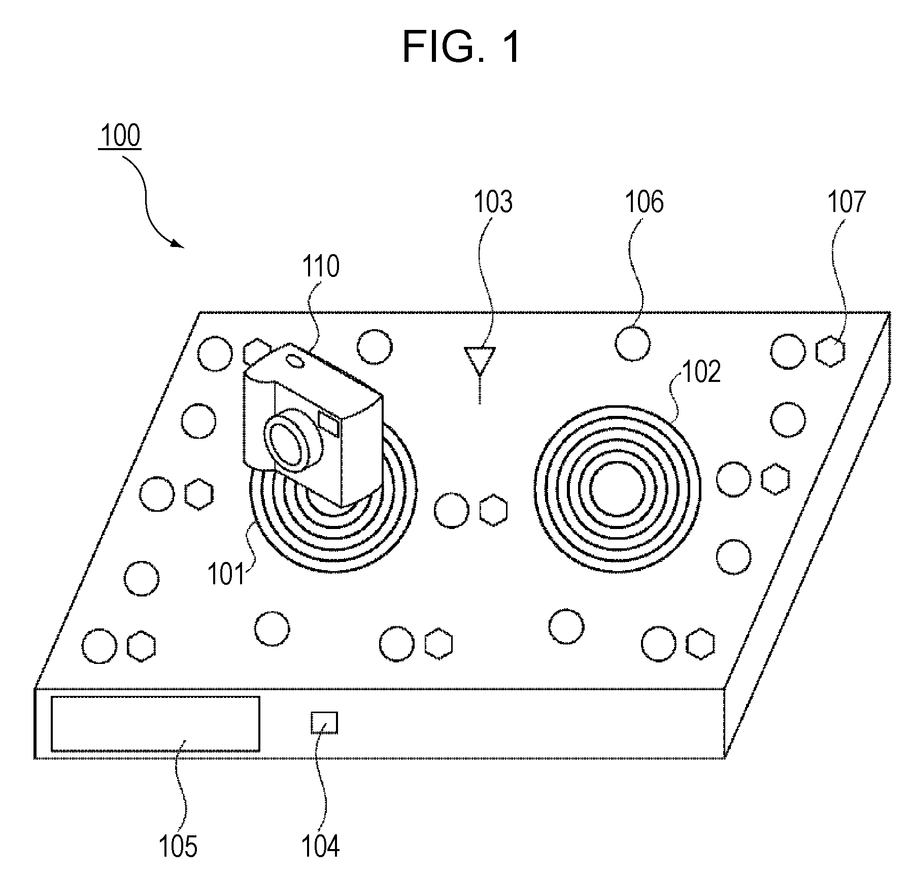
[0017]FIG. 1 shows a structure of a charging apparatus according to a first embodiment. A charging apparatus 100 includes two coils 101 and 102. A magnetic field generated by passing a current through each of the coils 101 and 102 causes a voltage to be generated, due to electromagnetic induction, across both ends of a coil in a device to be charged that is placed above the coil 101 or 102. The coils 101 and 102 may be exposed or may be covered with an outer case made of a non-conductive material such as plastic or a resin.

[0018]The charging apparatus 100 also includes an IC communication unit 103 used to communicate with an IC tag provided in a device being charged that is placed on the charging apparatus 100. An IC...


PUM


Abstract

A charging apparatus includes: a charging unit configured to perform a contactless charging operation for a placed external device; a detector configured to detect a position of a placed object; a determining unit configured to determine that the placed object is an external device compatible with the charging unit; and a control unit configured to control the charging unit such that, during the contactless charging operation for an external device compatible with the charging unit, the charging operation for the external device being charged is restricted when an object that is determined by the determining unit not to be an external device compatible with the charging unit, has been placed within a predetermined distance from the charging unit.

Description

BACKGROUND OF THE INVENTION[0001]1. Field of the Invention[0002]The present invention relates to a charging apparatus, and in particular to a charging apparatus that provides electric power to external devices using electromagnetic induction.[0003]2. Description of the Related Art[0004]Contactless charging apparatuses that use electromagnetic induction have been known. Such charging apparatuses utilize the principle of electromagnetic induction in which a magnetic field generated by an electric current flowing in a primary coil provided in a charging apparatus causes a voltage to be generated across both ends of a secondary coil provided in an external device. In these charging apparatuses, when a foreign object such as a piece of metal (for example, a coin) is placed within the magnetic field generated by the primary coil, an eddy-current flowing in the piece of metal may cause heat to be generated due to the internal resistance of the piece of metal.[0005]To address such a problem...

Claims


Application Information

Patent Timeline
Patent Type & Authority Applications(United States)
IPC IPC(8): H02J7/00
CPCH02J7/025H02J50/10H02J50/60H02J50/80H02J50/90
Inventor TANABE, AKIHIRO
Owner CANON KK
Why Eureka
Try Eureka