Framework for assembly around a gift, surprise or present

a technology for wrapping and gifts, applied in the direction of transportation and packaging, sustainable packaging industry, other domestic articles, etc., can solve the problems of difficult wrapping, difficult to wrap, and the toy is unlikely to fit in its original packaging, so as to achieve the effect of easy and quick construction

Inactive Publication Date: 2009-09-10
JONES PETER +1
View PDF19 Cites 0 Cited by
  • Summary
  • Abstract
  • Description
  • Claims
  • Application Information

AI Technical Summary

Benefits of technology

[0007]The primary objective of this invention is to provide a system of rods and connectors that allow the user to easily and quickly construct a cubic frame that will fit over a gift or present. There are four main components that are used to create the framework. A 3-dimensional corner fitting (FIGS. 1-3) that has three triangular spigots (or legs) protruding from a cube in the x, y and z axis. The second piece is an adaptor fitting (FIGS. 4-6) that is triangular shaped and has two spigots along the same axis. There are two extruded rods of differen...

Problems solved by technology

This creates a dilemma as the parent/guardian may opt to leave the gift unassembled and in the packaging in which it was bought.
However this means that once opened on the day of the celebration, the toy will require assembly before the child can play with it.
Further problems may be ...

Method used


Image

  • Framework for assembly around a gift, surprise or present
  • Framework for assembly around a gift, surprise or present
  • Framework for assembly around a gift, surprise or present

Examples


Embodiment Construction

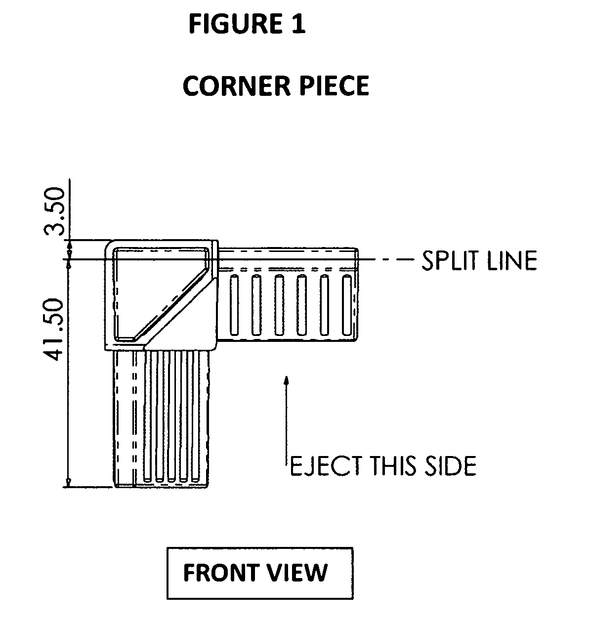
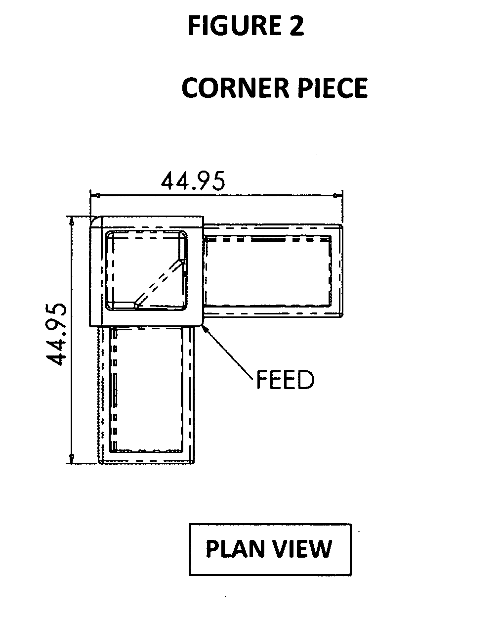
[0018]Both corner piece and adaptor have ribs (or a raised profile of lines) that helps create a firm fit when the rods are engaged on to the spigot. A triangular profile has been selected as this offers benefits over a rectangular or square profile. Firstly, less plastic is used and secondly when packaging the product two rods can be placed together with the hypotenuse faces together to reduce its packaged size.

[0019]The corner piece (FIGS. 1-3) and adaptor (FIGS. 4-6) are designed specifically for production through injection moulding and with appropriate cavities to ease the production process and reduce weight and material content.

[0020]The two rods have a specific tolerance so as to ensure a firm fit over the spigots and are of a rigid PVC material to achieve the required straightness over their length. They are to be manufactured as conventional Extrusions.

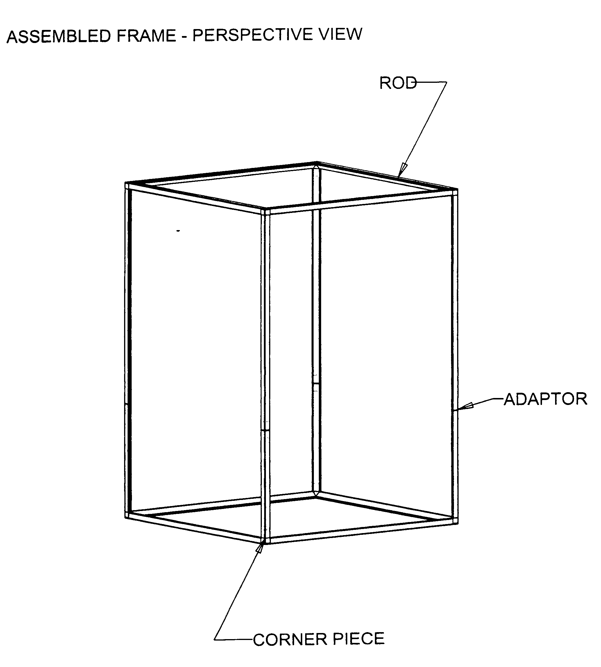
[0021]The packaged product will consist of eight corner fittings and twelve adaptors, suitable to create a 3 dimensional f...


PUM

PropertyMeasurementUnit
Angleaaaaaaaaaa
Flexibilityaaaaaaaaaa

Abstract

This invention is designed to provide a solution to a problem that exists when considering how to present a gift predominantly to a child. This is a plastic modular frame that is easily erected and fits over an assembled, tested and/or unusual shaped gift. By creating the cubic frame, it becomes easy to attach standard gift wrapping paper to the frame and conceal the gift inside. Rods and connecting spigots have a unique triangular profile and being produced in plastic are reusable to the consumer. Attached drawings show an assembled frame (FIG. 9) together with drawings of each of the main components; corner piece, adaptor and rod profile (FIGS. 1 to 8). See paragraph 0010 for full description of each drawing.

Description

[0001]This invention is designed specifically to solve a problem that exists when preparing certain gifts or presents, predominantly but not exclusively for children.Name of first Inventor:Peter JonesInventors' residence:21 Whinberry WayMoorsideOldhamGreater ManchesterPost code / Zip codeOL4 2NNCountry of residence:United KingdomTelephone:+44 161 678 9765e-mail:peter.jones@buildnwrap.comName of second Inventor:Philip DaleInventors' residence:9 Watermill CloughRoytonOldhamGreater ManchesterPost code / Zip codeOL2 5WBCountry of residence:United KingdomTelephone:+44 161 628 0164e-mail:phil.dale@buildnwrap.comREFERENCE TO RELATED APPLICATIONS[0002]A patent application has been made though the United Kingdom patent office. This is filed under application number GB0804580.9 with a filing date of 10 Mar. 2008. No priority is being claimed from the UK application.STATEMENT REGARDING FEDERALLY SPONSORED RESEARCH OR DEVELOPMENT[0003]Not applicableREFERENCE TO SEQUENCE LISTING, A TABLE, OR A COMPU...

Claims


Application Information

Patent Timeline
IPC IPC(8): B32B1/08
CPCB65D61/00Y10T428/1352Y02W30/80B65D57/00
Inventor JONES, PETERDALE, PHILIP
Owner JONES PETER
Why Eureka
Try Eureka