
Modular and mobile waste and/or hazardous liquid containment and collection shower system

Active Publication Date: 2007-03-01
DECHARD ALBERT +1
View PDF21 Cites 9 Cited by
  • Summary
  • Abstract
  • Description
  • Claims
  • Application Information

AI Technical Summary

Benefits of technology

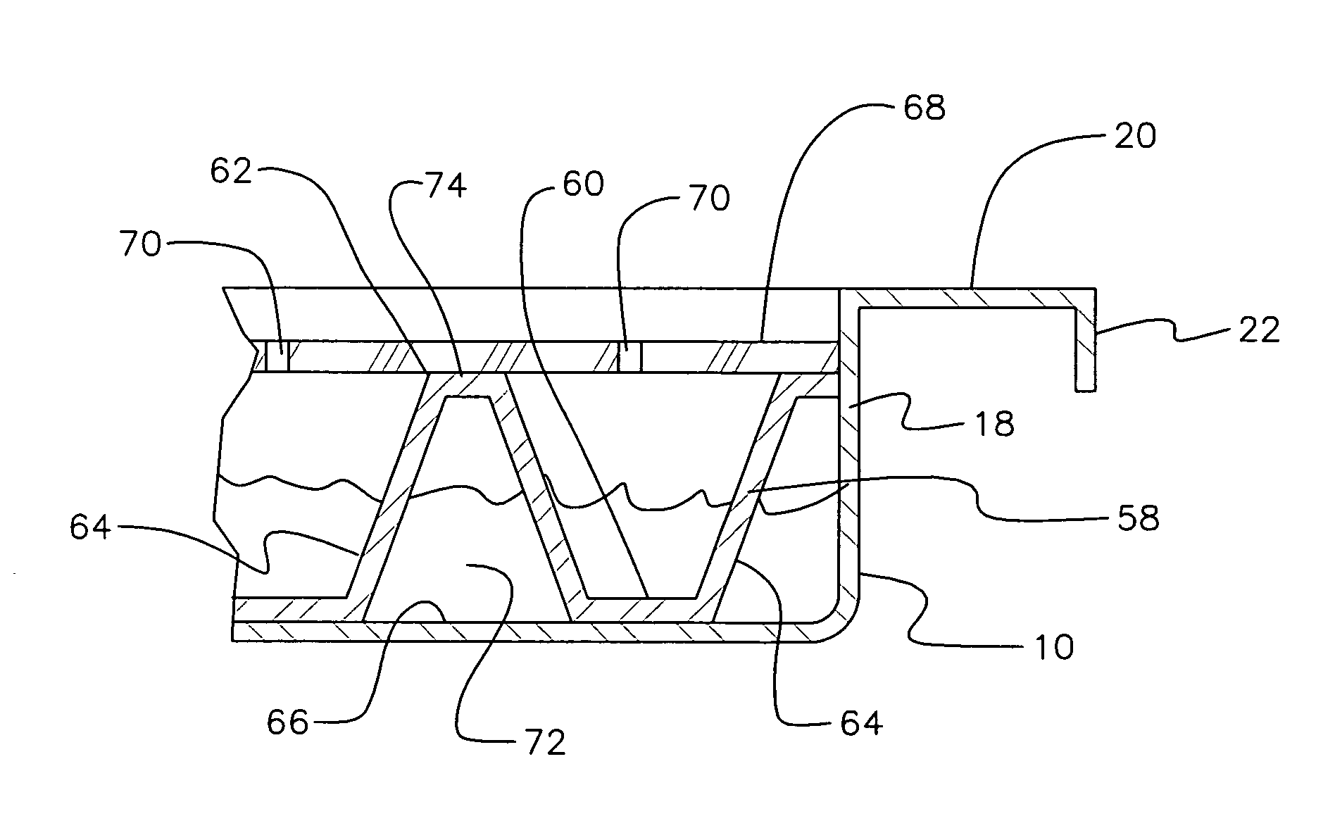
[0011] I have invented an improved hazardous liquid and / or waste water capture, collection, and containment shower system. My improved system is both modular and extremely mobile. Accordingly, it can be quickly employed and removed in a desired location. The system employs small modular and light-weight pans constructed from a liquid impervious material. Each pan has a bottom layer and four integrally attached upstanding walls. Each wall has a horizontally disposed outwardly extending ledge and a downwardly depending lip which permits any one pan to affix to any one adjoining pan. Of the four lips, each pan has two wide-lipped sides and two narrow-lipped sides. When two pans are connected, a wide-lipped side of one pan attaches and overlaps to a narrow-lipped side of an adjoining pan thereby interlocking two pans. Since each pan is light weight, a hazardous liquid and / or waste water shower system can be quickly and easily constructed and thereafter taken apart, moved and re-constructed in a different location.
[0013] When constructing a shower system wherein four corners of four separate pans adjoin, a brace, having a four leg, star like configuration is used to ensure a strong connection between the four pans. In a preferred embodiment, the brace employs four legs disposed at 90 degrees from each other. The aforementioned system would be applicable, for example, when two longitudinal columns of pans are employed in a constructed shower system. Further, a valve network can be provided at the four corner junction, proximal to the four leg brace, to again allow the user greater flexibility in controlling the direction and destination of fluids captured by the shower system in each pan. This aforementioned embodiment is extremely useful when two adjoining pans are capturing water or fluids of different types and it is desirous to maintain their separation. An example of this use is a hospital triage treating people or workers from two different infected sites of two different biological agents or chemicals.
[0015] Although the preferred embodiment for the present invention is a shower system, alternate uses for the pan can satisfy needs and deficiencies seen in the prior art. For example, the modular pans can be employed in the food industry underneath racks in refrigerators, freezers and meat lockers to capture any liquids spilling from said racks thereby avoiding contamination of the food contained therein. This would be most useful in the event of a power outrage to these food containment refrigeration systems. Further, the modular pans can be employed underneath stretchers in ambulances and treatment or surgery tables in both emergency and surgical rooms of hospitals and veterinarian clinics. Still further, the modular pans can be employed “in-line” in manufacturing facilities to capture leaks and spills of chemicals and other hazardous materials from fifty-five gallon drums. These hazardous liquids include, but are not limited to, lacquer thinners, industrial cleaners, solvents, oils, gasoline and diesel fuel.

Problems solved by technology

This waste water is no longer allowed to simply enter the sewer system or run off into the underground aquifer or nearest body of water.
However, if the needs of the user are mobile, or if the apparatus needs to be expanded, due to the object to be rinsed being larger than what the apparatus can handle, a problem arises.
It is not easily modifiable.
On the other hand, this system is not easily made mobile nor does it have the ability to be modular without making alterations to the overall design of the device once constructed.
Alterations can be made, but requires an increase in overhead costs and a delay in use of the apparatus thereby temporarily disabling the ability to generate a stream of income from said apparatus.
Other problems with hazardous liquid and waste water containment and collection have also recently arisen as to wars, crime, terrorism and environmental accidents.
In particular, it is not uncommon for businesses, public facilities and land areas to be exposed or infected to deadly biological or chemical substances that are extremely hazardous to remove.
However, to allow the rinse water to simply run off and into ground or sewer would be self-defeating and negate the reason for cleaning the affected area in the first place.
To date, the prior art lacks a system which can adequately handle the necessary capture, collection and containment of the waste water resulting from hazardous clean-up showers, such as those required in a Hot Zone.
The deficiencies seen in the prior art include a lack of any system which can be quickly deployed and / or enlarged at a moment's notice.
This deficiency could prove to be critical in the event of a large scale biological terrorist attack.
This would prove to be difficult or impossible with the existing state of the art.
Further to the occurrence of biological or chemical attacks or accidents, if a large portion of society was exposed, it is obvious that those infected would seek immediate medical attention inundating hospitals and other emergency facilities.
The people infected may end up exposing a large percentage of the health care providers whose help they seek if not properly cleansed prior to examination or treatment.
Nor does a system exist that can be modified rapidly to accommodate a rising number of patients over a short time period.
Other problems exist with hazardous liquid capture and containment.
For instance, when transferring hazardous liquids from fifty-five gallon drums, it is not uncommon to have spills or leaks.

Method used


Image

  • Modular and mobile waste and/or hazardous liquid containment and collection shower system
  • Modular and mobile waste and/or hazardous liquid containment and collection shower system
  • Modular and mobile waste and/or hazardous liquid containment and collection shower system

Examples


Embodiment Construction

, contained herein below, may be better understood when accompanied by a brief description of the drawings, wherein:

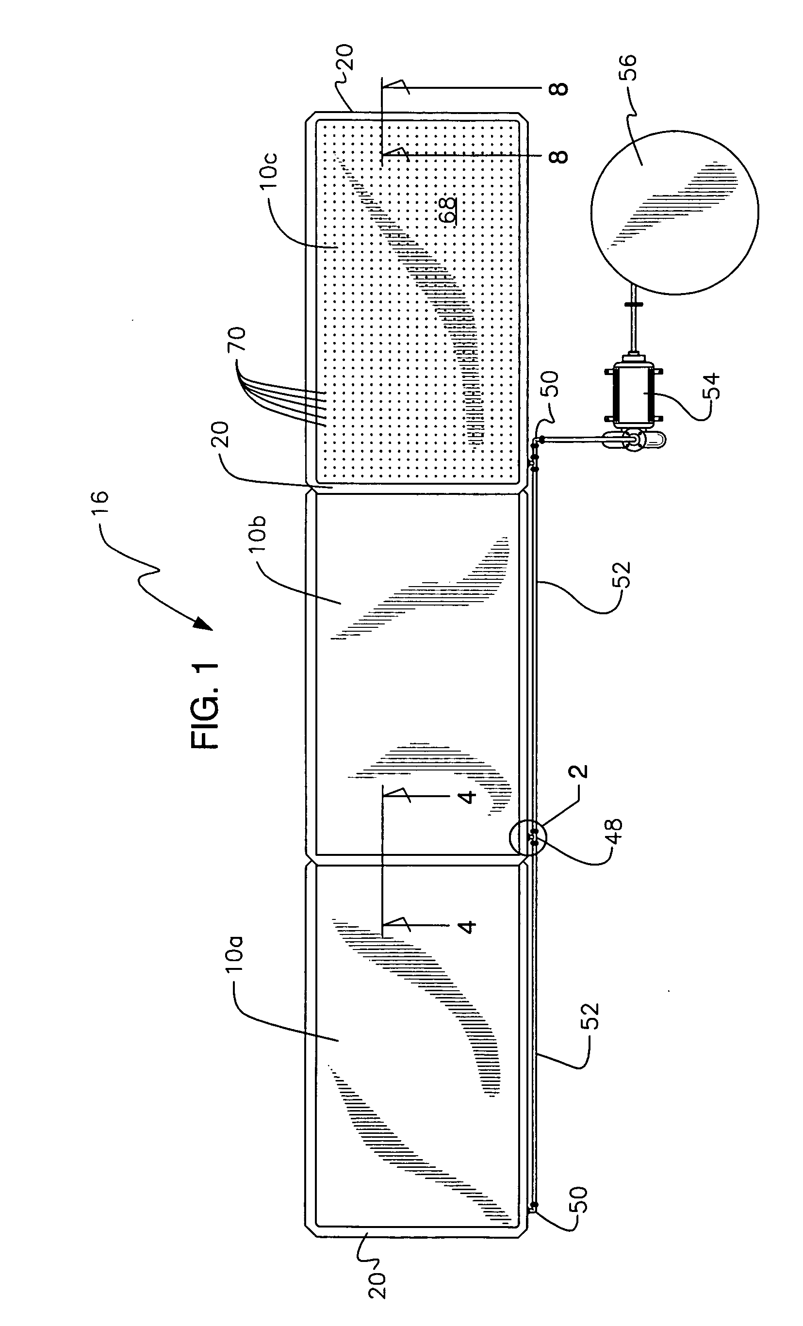
[0017]FIG. 1 is a top plan view of a hazardous and / or waste water collection and containment shower system of the present invention, illustrating the use of multiple modular pans or water impervious barriers;

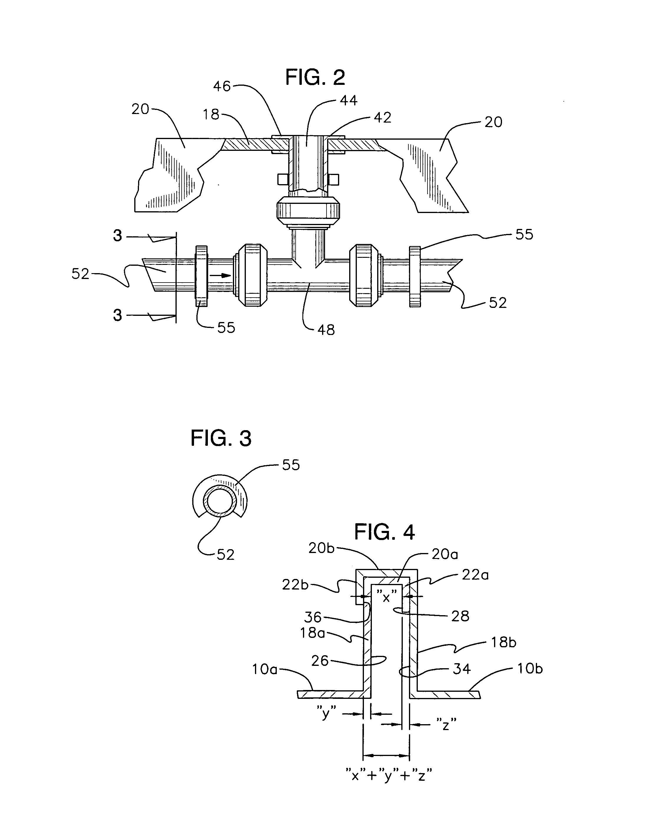
[0018]FIG. 2 is a top plan view, partially in section, of a valve connection employed in any one of the modular pans employed in the present invention;

[0019]FIG. 3 is a cross section view of FIG. 2 along lines 3-3 of FIG. 2;

[0020]FIG. 4 is a cross-sectional view, along lines 4-4 of FIG. 1, illustrating how two modular pans interconnect by way of friction fit along top edges of upstanding walls thereof;

[0021]FIG. 5 is a perspective view of a corner section of a modular pan employed in the present invention;

[0022]FIG. 6 is a side plan view, partially in section, of side edges of two modular pans illustrating the manner in which any two modular pans interconnect;...


PUM


Abstract

A waste water and hazardous chemical collection system is provided. The system includes a bottom pan having a plurality of vertically disposed walls, a multitude of outwardly horizontally projecting ledges and a plurality of downwardly depending lips. Each pan further includes a drainage waffle inserted within said pan. A work surface is applied to a top surface of said drainage waffle. A plurality of holes is formed in said work surface permitting any liquids that make contact to the work surface to drain there through and into an area of the bottom pan. A pump is connected to said pan for withdrawing liquids therefrom. The system includes a water source for each pan thereby creating a shower system.

Description

BACKGROUND OF THE INVENTION [0001] 1. Field of Invention [0002] The present invention relates to hazardous and / or waste liquid collection and containment. More particularly, it relates to a modular and mobile shower system for capturing, containing and collecting hazardous liquids and / or waste water resulting from leaks or from a rinsing procedure of people, machines or other objects that emit or have adhered thereto, substances that are hazardous to the environment if allowed to run-off. [0003] 2. Description of the Prior Art [0004] Hazardous liquid and waste water collection is known in the prior art. Due to rising concerns that the environment is becoming polluted at an alarming rate by hazardous chemicals, governments, both State and Federal, and those in other countries have begun mandating that water runoff from shower and rinsing procedures be contained and collected for proper disposable to avoid further contamination of the environment. For instance, the simple process of c...

Claims


Application Information

Patent Timeline
IPC IPC(8): E03B7/08
CPCA47K3/286E03F1/00Y10T137/5762Y10T137/8593
Inventor DECHARD, ALBERTSIMINSKI, CHARLES D.
Owner DECHARD ALBERT
Learn More