Combination Ultrasound-Phototherapy Transducer

a transducer and ultrasound technology, applied in the field of ultrasonics, can solve the problem that the commercial devices on the market have not solved this problem directly

Active Publication Date: 2009-09-10
SOUND SURGICAL TECH +1
View PDF31 Cites 24 Cited by
  • Summary
  • Abstract
  • Description
  • Claims
  • Application Information

AI Technical Summary

Benefits of technology

[0013]Commercial devices on the market have not solved this problem directly, but have provided for independent acoustic and optical sources (handpieces) powered from the same console. Conventional systems have relied on conventional piezoelectric transducer technology, which generally includes a solid metal front face (the side which faces the patient).

Problems solved by technology

Commercial devices on the market have not solved this problem directly, but have provided for independent acoustic and optical sources (handpieces) powered from the same console.

Method used


Image

  • Combination Ultrasound-Phototherapy Transducer
  • Combination Ultrasound-Phototherapy Transducer
  • Combination Ultrasound-Phototherapy Transducer

Examples


Embodiment Construction

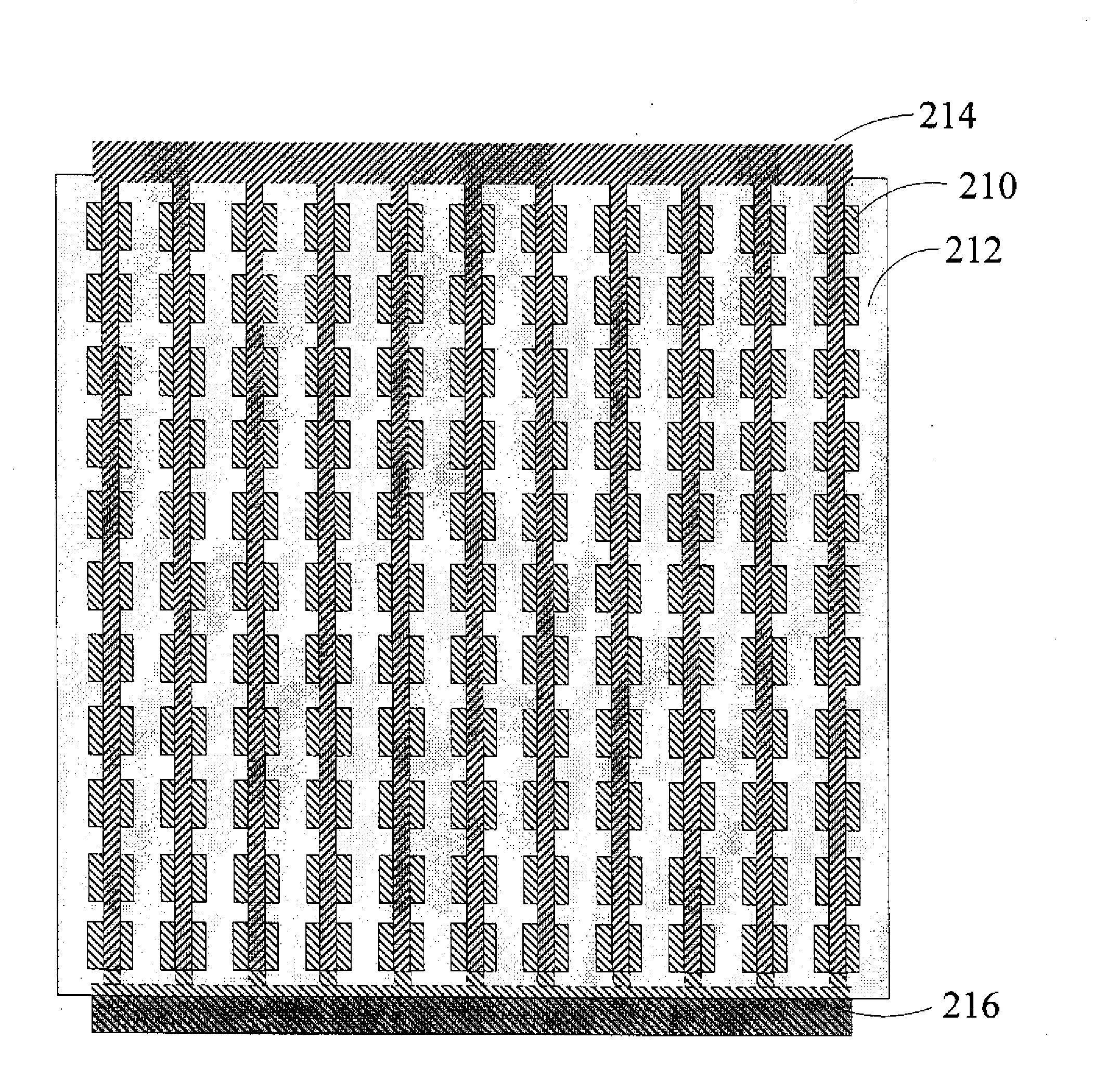
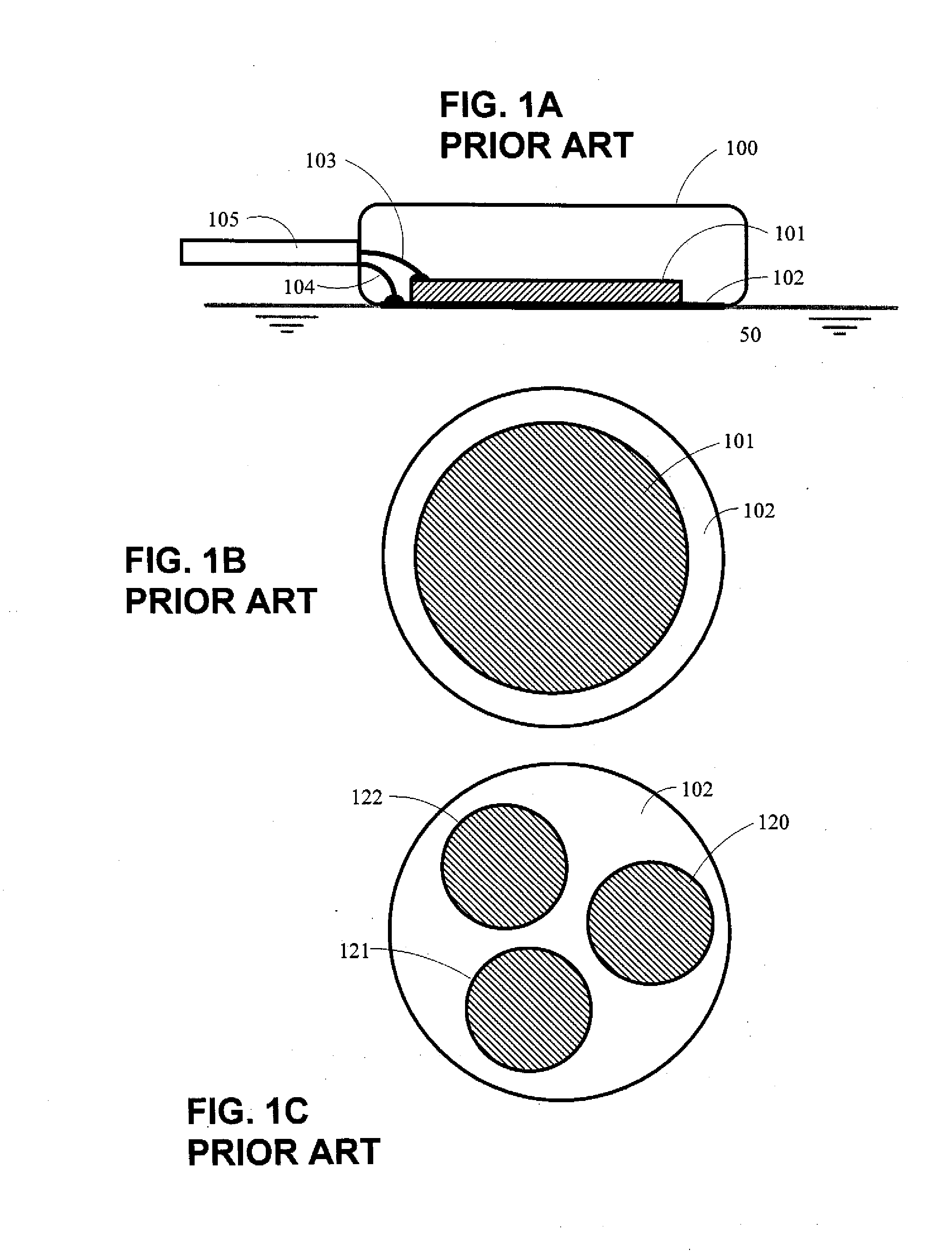
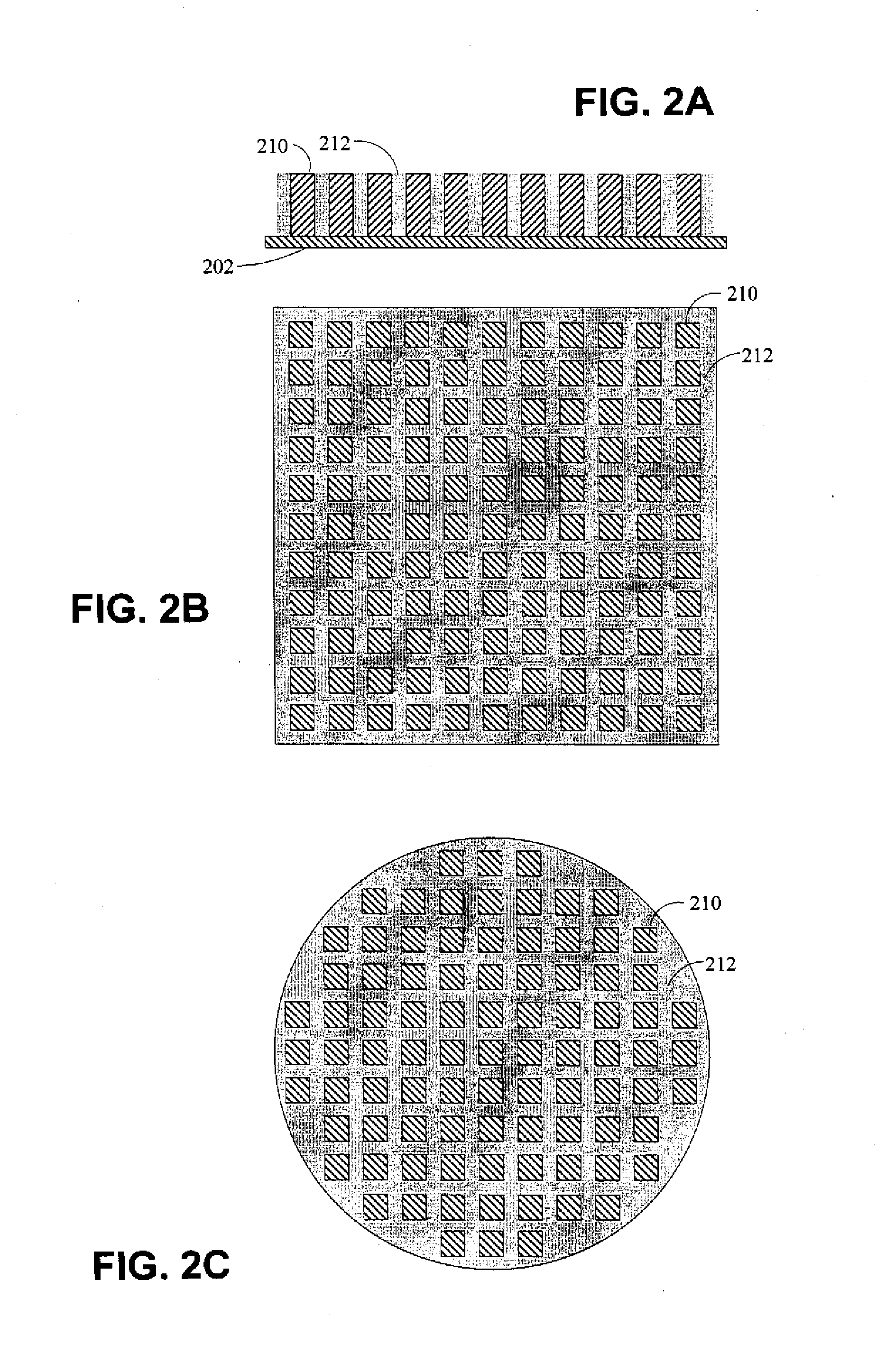
[0026]FIGS. 1A-1C depict a soundhead of design typical of the prior art. FIG. 1A is a simplified cutaway diagram of the soundhead in contact with tissue 50. The scanhead consists of housing 100, which contains the ultrasound transducer element 101, attached to the faceplate 102 which makes contact with tissue 50. The faceplate 50 is typically metal, either stainless steel or aluminum. Cable 105 attaches to housing 100. Lead 103 of cable 105 attaches to the rear of transducer element 101, and lead 104 of cable 105 attaches to the front of transducer element 101, typically through an electrical connection to the metal faceplate 102. Other means of connection have been used, including “wrap around” electrodes on transducer element 102 such that the electrical connection to the front of the transducer element is brought around to an isolated portion of the rear of the transducer element. The exact means are not necessarily important to the present invention.

[0027]The current art in ultr...


PUM


Abstract

A soundhead of a treatment device is provided that enables a volume of tissue located beneath the soundhead to simultaneously receive ultrasound and light stimulation. According to one embodiment, the soundhead includes an ultrasound transducer, a light source, and a faceplate extending across a face of the transducer for providing a tissue contacting and ultrasound energy coupling surface of the soundhead. The faceplate is transparent or translucent to the light generated by the light source. Alternate embodiments including externally mounted light sources are also disclosed.

Description

CROSS-REFERENCE TO RELATED APPLICATIONS[0001]This application claims the benefit under 35 USC §119(e) of U.S. Provisional Patent Application No. 61 / 033,470, filed Mar. 4, 2008.BACKGROUND OF THE INVENTION[0002]The present invention relates to Ultrasonics, more specifically, to the application of ultrasound energy for physical therapy and wound or tissue treatment.[0003]Ultrasound energy has been used for over 50 years as a therapeutic treatment modality in physical therapy and sports medicine. Recently, lower intensity ultrasound has been used to accelerate the healing of bone fractures and both fresh and long term non-healing wounds. For purpose of example, U.S. Pat. No. 7,282,036 B2 issued to Masuda, U.S. Pat. No. 7,195,603 B2 issued to Yamazaki et al., U.S. Pat. No. 7,022,089 B2 issued to Ooba et al., U.S. Pat. No. 6,273,864 B1 issued to Duarte et al., U.S. Pat. No. 5,690,608 issued to Watanabe et al., U.S. Pat. No. 5,549,544 issued to Young et al., U.S. Pat. No. 5,520,612 issued ...

Claims


Application Information

Patent Timeline
Patent Type & Authority Applications(United States)
IPC IPC(8): A61N7/00A61B18/18
CPCA61B8/06A61B8/4455A61M37/0092A61N5/0616A61N7/00A61N5/06A61N2005/0652A61N2005/067A61N2007/0017A61N2007/0043A61N2005/0644A61N5/067A61N2005/0643
Inventor SCHAFER, MARK E.ALLER, BRADY
Owner SOUND SURGICAL TECH
Why Eureka
Try Eureka