Chair-type Massaging Machine

a massaging machine and chair technology, applied in the field of chair-type massaging machines, can solve the problem that the heel massaging portion may not be able to apply effective pressure to the heel, and achieve the effect of effective massage and enhanced physical locking effect of the plantar-arch projection

Inactive Publication Date: 2009-09-10
FAMILY INADA
View PDF4 Cites 12 Cited by
  • Summary
  • Abstract
  • Description
  • Claims
  • Application Information

AI Technical Summary

Benefits of technology

[0013]In this case, the plantar-arch projection is prevented from being flattened due to a cover member and the like covering the plantar-arch projection. Therefore, t

Problems solved by technology

This may lead to the following problem.
Hence, the heel massaging

Method used


Image

  • Chair-type Massaging Machine
  • Chair-type Massaging Machine
  • Chair-type Massaging Machine

Examples


Embodiment Construction

[0036]A preferred embodiment of the invention will hereinbelow be described with reference to the accompanying drawings.

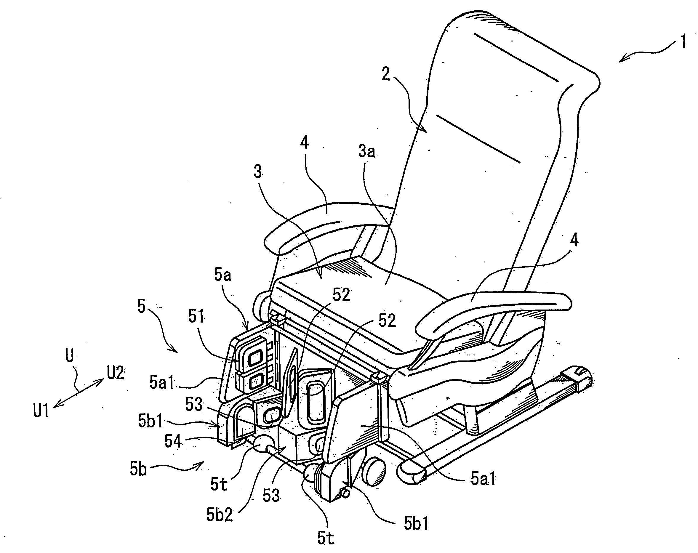
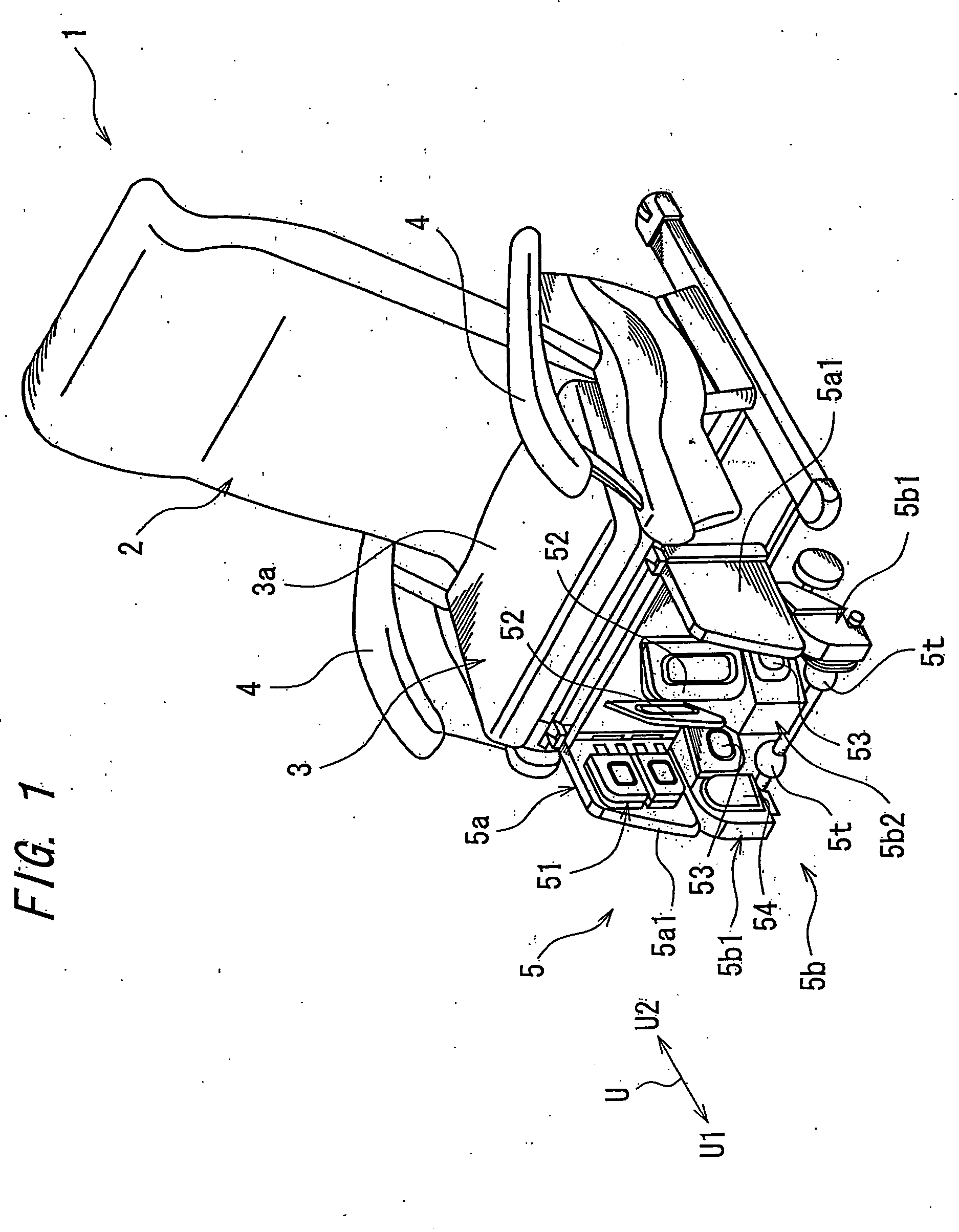
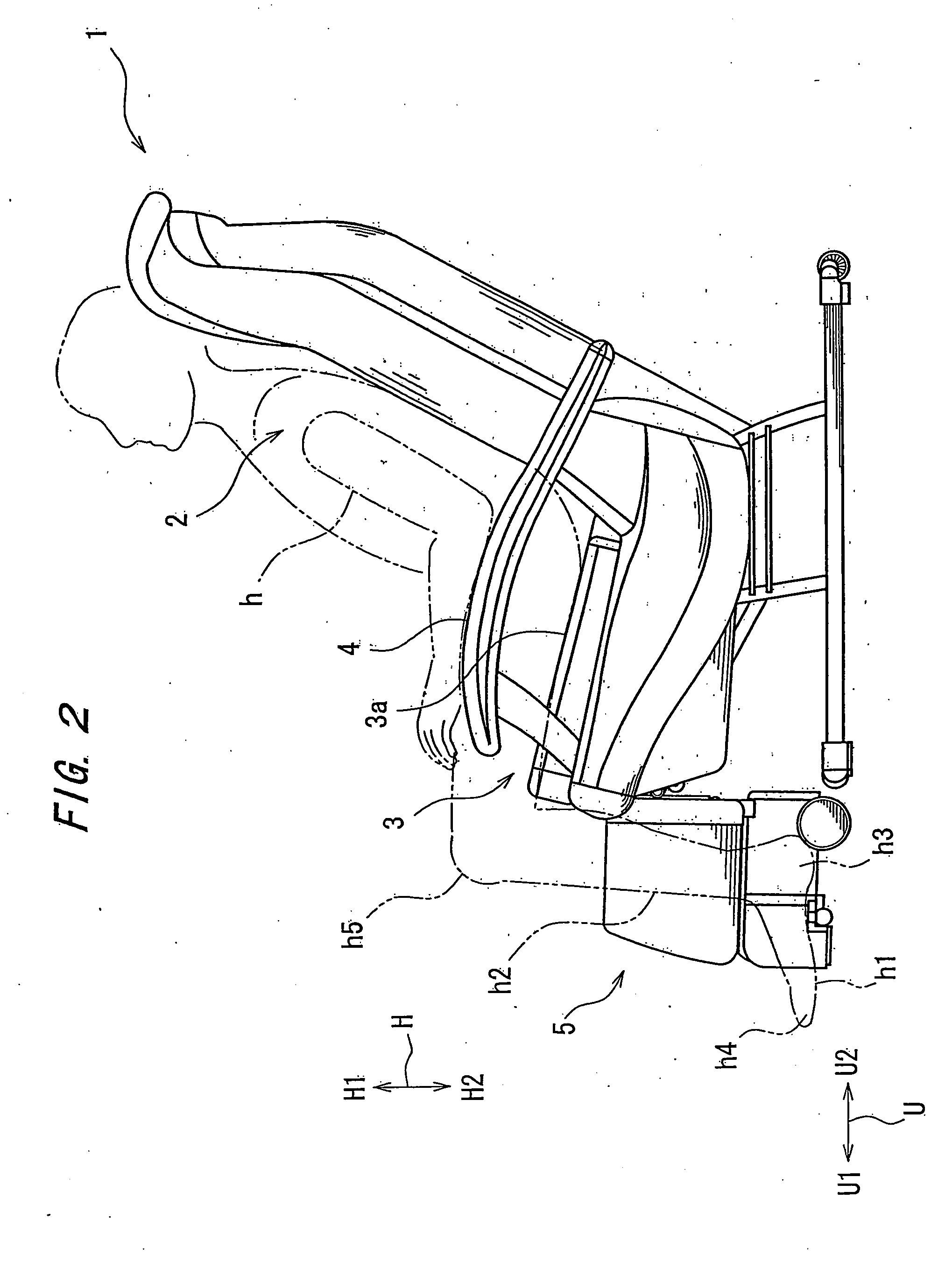
[0037]FIG. 1 is a perspective view showing the whole body of a chair-type massaging machine 1 according to one embodiment of the invention, whereas FIG. 2 is a side view thereof. As shown in these figures, the chair-type massaging machine 1 includes: a backrest 2 capable of supporting a seated massagee h on the back and the head; a seat 3, an upper surface of which defines a seat surface 3a capable of supporting the hips and thighs of the massagee h; an armrest 4 disposed on lateral sides of the machine for supporting the arms of the massagee h; a footrest 5 for the massagee h to place the calves and soles therein. FIG. 1 shows the footrest 5 removed of a cover in order to disclose an internal mechanism of the footrest 5.

[0038]Although not shown in the figures, massaging members, such as an air cell, massaging element and vibrator, for applying massage to the massa...


PUM


Abstract

A chair-type massaging machine includes: a seat surface 3a for a massagee h to be seated thereon; a plantar-arch projection 5t for the seated massagee h to place plantar arches h6 thereon; and a heel-massaging air cell 53 capable of clamping and pressing heels h3 in a feet-resting position where the plantar arches h6 rest on the plantar-arch projection 5t, and effectively massages the heels and soles.

Description

TECHNICAL FIELD[0001]The present invention relates to a chair-type massaging machine.BACKGROUND ART[0002]Some of the chair-type massaging machines are adapted to massage heels and soles. Japanese Laid Open Patent Application Publication No. 2004-215938 (hereinafter, referred to as “Prior-Art Document”), for example, discloses a chair-type massaging machine which includes: a sole support surface for supporting massagee's soles rested thereon, and a heel support surface upstanding from a rear side of the sole support surface for supporting heels on the rear sides thereof, wherein the heel support surface is provided with a heel massaging portion for clamping and pressing a rear part of each heel, and wherein the sole support surface is provided with a sole massaging portion for pressing each sole.DISCLOSURE OF THE INVENTION[0003]A heel of human body is configured to be progressively decreased in width toward the rear end thereof. Therefore, a pressing force of the heel massaging porti...

Claims


Application Information

Patent Timeline
IPC IPC(8): A61H1/00
CPCA61H9/0078A61H2201/0149A61H2205/125A61H2205/10A61H2205/106A61H2203/0431A61H7/007A61H15/00A61H2015/0064A61H2015/005A61H2205/12
Inventor ENAMI, KOUICHIKIM, MYONGSIK
Owner FAMILY INADA
Why Eureka
Try Eureka