Visual electrode ablation systems

a technology of ablation system and visual electrode, which is applied in the field of medical devices, can solve the problems of difficult direct visualization and subsequent manipulation of heart tissue, and the inability to manipulate the local tissue, so as to facilitate the formation of a seal, reduce saline discharge, and widen the effect of the area

Active Publication Date: 2009-09-10
INTUITIVE SURGICAL OPERATIONS INC
View PDF104 Cites 146 Cited by
  • Summary
  • Abstract
  • Description
  • Claims
  • Application Information

AI Technical Summary

Benefits of technology

[0014]Generally, the embodiments of a tissue imaging and manipulation device depicted in the present invention meet the challenge and solve the problem of accessing regions of the body which are typically difficult to access. The design and control of the catheter shaft and the distal tip of the device as disclosed here provide a device uniquely capable of accessing a region such as the human heart, which is a region not only difficult to access, but which also has continuous blood flow. The blood flow provides a barrier to visualizing the local tissue, which in turn makes any manipulation at the local tissue nearly impossible. The unique elements that form the catheter shaft and the distal tip of the device, including the separate control of the shaft and tip and several optional modes of manipulation of either or both, provide for a device adaptable to addressing the challenges inherent in intravascular access and manipulation of heart tissue, and for accomplishing a procedure in any other difficult-to-access region in the body which is bathed in a medium that interfers with visualization.
[0030]Aside from visual confirmation of lesion formation, unobstructed visual confirmation of the tissue during ablation may allow for the monitoring of bubble formation upon the tissue surface as indications of potential endocardial disruptions. Software incorporating algorithms using edge detection technology may be utilized to monitor the tissue surface for parameters such as the quantity and / or rate of bubble formation within the visual field. Such monitoring may be utilized to automatically to reduce or cease power levels to prevent any endocardial disruptions from occurring as a safety measure.

Problems solved by technology

The blood flow provides a barrier to visualizing the local tissue, which in turn makes any manipulation at the local tissue nearly impossible.
Blood is continuously flowing through the heart at all times, and as such presents a challenge to direct visualization and subsequent manipulation of heart tissue.

Method used


Image

  • Visual electrode ablation systems
  • Visual electrode ablation systems
  • Visual electrode ablation systems

Examples


Embodiment Construction

[0097]Various exemplary embodiments of the invention are described below. Reference is made to these examples in a non-limiting sense. They are provided to illustrate more broadly applicable aspects of the present invention. Various changes may be made to the invention described and equivalents may be substituted without departing from the true spirit and scope of the invention. In addition, many modifications may be made to adapt a particular situation, material, composition of matter, process, process act(s) or step(s) to the objective(s), spirit or scope of the present invention. All such modifications are intended to be within the scope of the claims made herein.

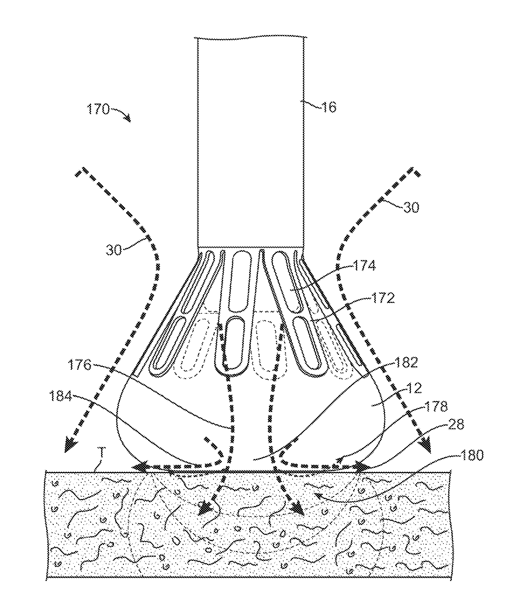
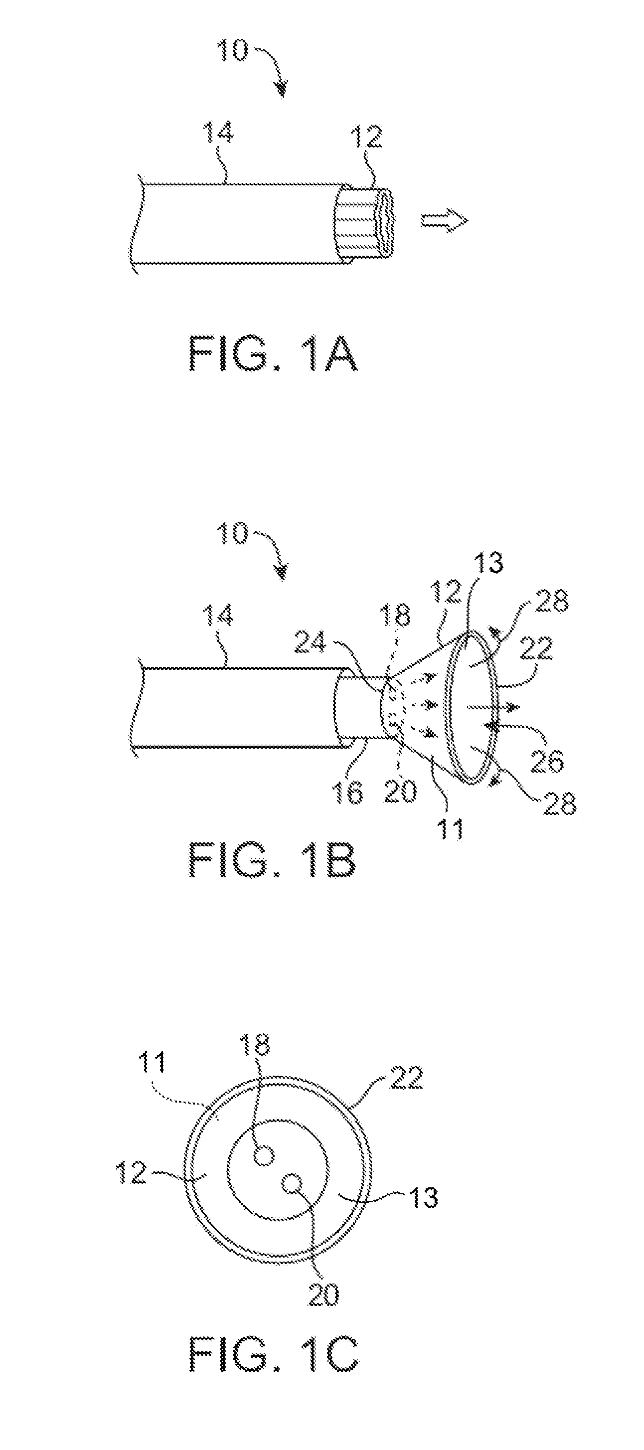
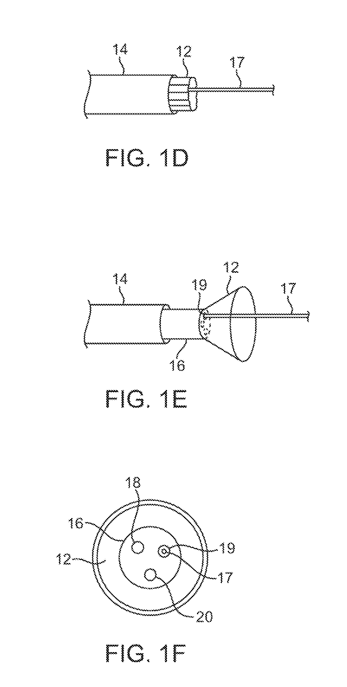
[0098]The tissue-imaging and manipulation apparatus of the invention is able to provide real-time images in vivo of tissue regions within a body lumen such as a heart, which are filled with blood flowing dynamically through the region. The apparatus is also able to provide intravascular tools and instruments for performi...


PUM


Abstract

Visual electrode ablation systems are described herein which include a deployment catheter and an attached imaging hood deployable into an expanded configuration. In use, the imaging hood is placed against or adjacent to a region of tissue to be imaged in a body lumen that is normally filled with an opaque bodily fluid such as blood. A translucent or transparent fluid, such as saline, can be pumped into the imaging hood until the fluid displaces any blood, thereby leaving a clear region of tissue to be imaged via an imaging element in the deployment catheter. An electric current may be passed through the fluid such that it passes directly to the tissue region being imaged and the electrical energy is conducted through the fluid without the need for a separate ablation probe or instrument to ablate the tissue being viewed.

Description

CROSS-REFERENCE TO RELATED APPLICATIONS[0001]This application is a continuation of U.S. patent application Ser. No. 12 / 118,439 filed May 9, 2008 which claims the benefit of priority to U.S. Prov. Pat. App. 60 / 917,487 filed May 11, 2007, each of which is incorporated herein by reference in its entirety.FIELD OF THE INVENTION[0002]The present invention relates generally to medical devices used for accessing, visualizing, and / or treating regions of tissue within a body. More particularly, the present invention relates to methods and apparatus for intravascularly accessing regions within the body, such as within the heart, and ablating tissue regions via energy delivery through an electrolytic fluid through which the tissue to be treated is also visualized.BACKGROUND OF THE INVENTION[0003]Conventional devices for accessing and visualizing interior regions of a body lumen are known. For example, ultrasound devices have been used to produce images from within a body in vivo. Ultrasound ha...

Claims


Application Information

Patent Timeline
Patent Type & Authority Applications(United States)
IPC IPC(8): A61B18/14A61B18/20A61N7/00
CPCA61B1/00089A61B1/012A61B18/1492A61B2017/00106A61B2018/00214A61B2018/00642A61B2018/00839A61B2018/1472A61B2218/002A61B2018/00577A61B2018/00809
Inventor WILLIS, N. PARKERMALCHANO, ZACHARY J.ROTHE, CHRIS A.SAADAT, VAHIDPEH, RUEY-FENGMILLER, DAVIDTAM, EDMUND
Owner INTUITIVE SURGICAL OPERATIONS INC
Why Eureka
Try Eureka