Upright extractor
a technology of extractor and extractor body, which is applied in the direction of vacuum cleaners, floor scrubbing machines, carpet cleaners, etc., can solve the problems of undesirable user, new set of problems for users, and residual moisture in the surfa
- Summary
- Abstract
- Description
- Claims
- Application Information
AI Technical Summary
Benefits of technology
Problems solved by technology
Method used
Image

Examples
first embodiment
[0055]The elongated belt guard 178, in effect, combines the end arm 130 and belt guard 154 of the first embodiment by extending the belt guard 154 to surround and include the end arm 130. The elongated belt guard 178 comprises an inwardly-extending flange 180 about a perimeter thereof and also includes two openings 190 therethrough. Each opening is configured to receive one of two conventional screws 192. The screws 192 are configured for receipt by each of two corresponding bosses (not shown) positioned on an interior surface of the belt cover 174. The elongated belt guard 178 further comprises a recess 194 configured to receive a bearing 196. The bearing 196 is adapted to receive a tip of the shaft of the drive motor 116.
[0056]When assembled, the screws 192 extend through the openings 190 and into the bosses on the interior of the brush cover 174 to couple the brush cover 174 and elongated belt guard 178 and to define a belt chamber (not shown) therebetween. The roller element 120...
second embodiment
[0057]In order to provide reversibility of the roller element 120 in the second embodiment as discussed hereinafter, a brush gear (not shown) and end cap (not shown) on the side of the roller assembly 170 substantially identical to the sides of the roller assembly 118 can have a size and configuration identical to the brush gear portion of the combination brush gear and end cap 172. This provides both sides of the roller element 120 with gear teeth 182 of the size and configuration necessary for proper engagement with the drive belt 176.
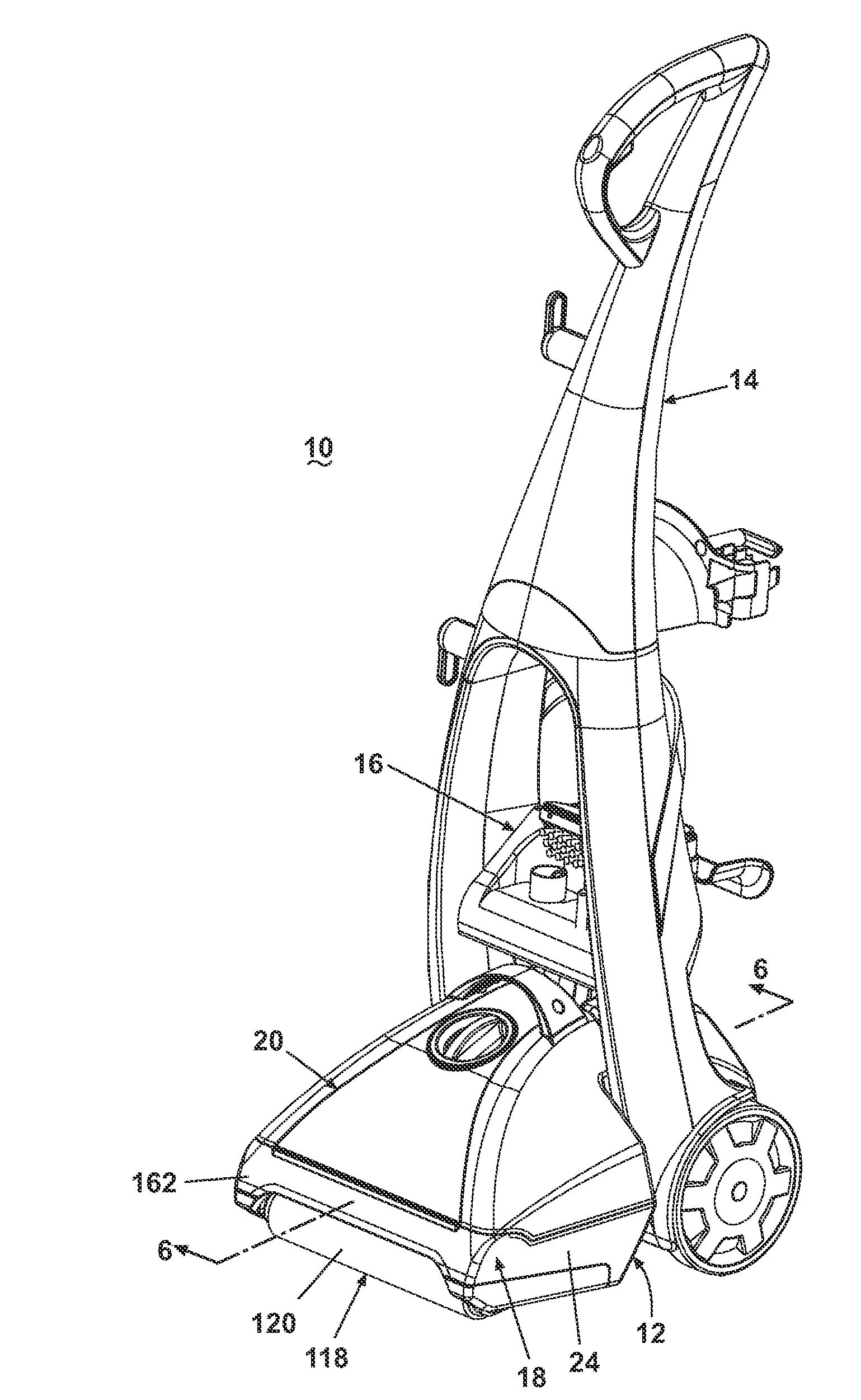
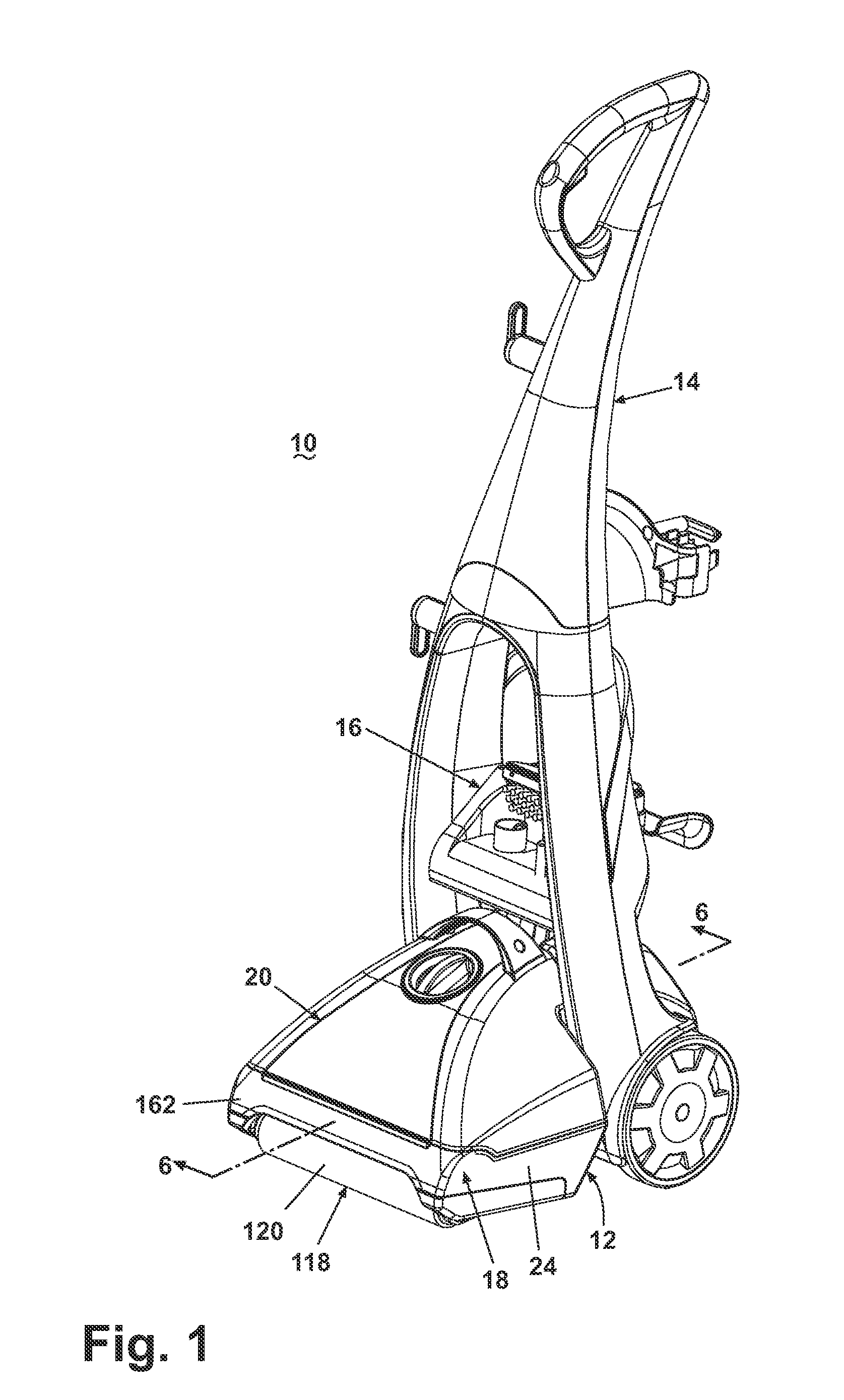
[0058]The roller element 120 can be removed for cleaning and replacement. To complete such an operation, the sole plate 162 can be accessed by the user from beneath the foot assembly 12 and can be removed via commonly known mechanical fasteners, such as screws or snaps. The sole plate 162 can be removed, thus releasing the roller assembly 118, 170 from the foot assembly 12 at the base mounting end 152. The end arms 130 can be removed from the axle 12...
PUM
 Abstract
Description
Claims
Application Information
 - Generate Ideas
- Intellectual Property
- Life Sciences
- Materials
- Tech Scout
- Unparalleled Data Quality
- Higher Quality Content
- 60% Fewer Hallucinations
Browse by: Latest US Patents, China's latest patents, Technical Efficacy Thesaurus, Application Domain, Technology Topic, Popular Technical Reports.
© 2025 PatSnap. All rights reserved.Legal|Privacy policy|Modern Slavery Act Transparency Statement|Sitemap|About US| Contact US: help@patsnap.com