Automated hinge assembly

a hinge assembly and automatic technology, applied in the field of hinges, can solve the problems of inconvenient operation of the hinge, time-consuming, and inconvenience of opening the cover, and achieve the effect of convenient and time-saving us

Inactive Publication Date: 2009-09-17
SHIN ZU SHING
View PDF15 Cites 4 Cited by
  • Summary
  • Abstract
  • Description
  • Claims
  • Application Information

AI Technical Summary

Benefits of technology

[0010]In such a manner, the cover mounted with the leaf connecting with the twisted torsion spring, or preferably with the leaf connected with the stationary bracket is able to pivot automatically relative to the body...

Problems solved by technology

However, conventional hinges require an external force to be applie...

Method used


Image

  • Automated hinge assembly
  • Automated hinge assembly
  • Automated hinge assembly

Examples


Embodiment Construction

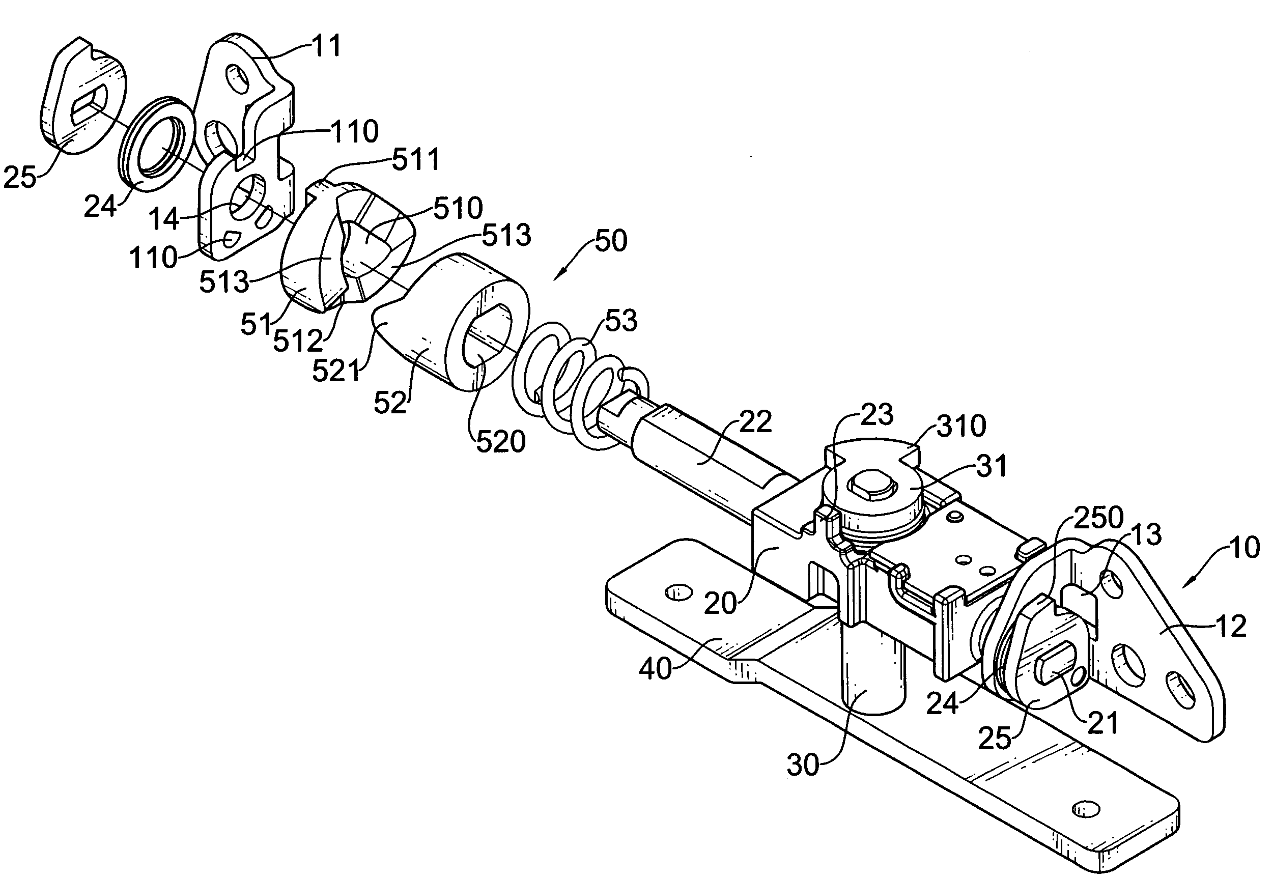
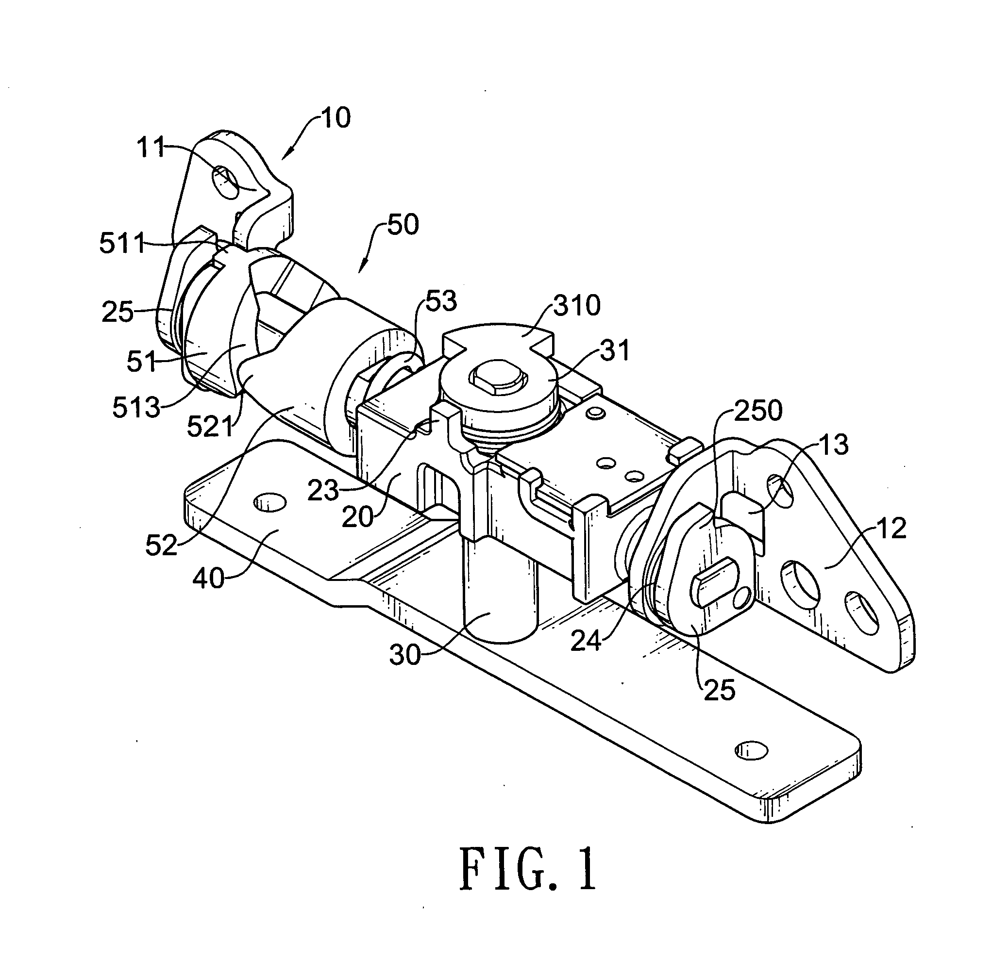
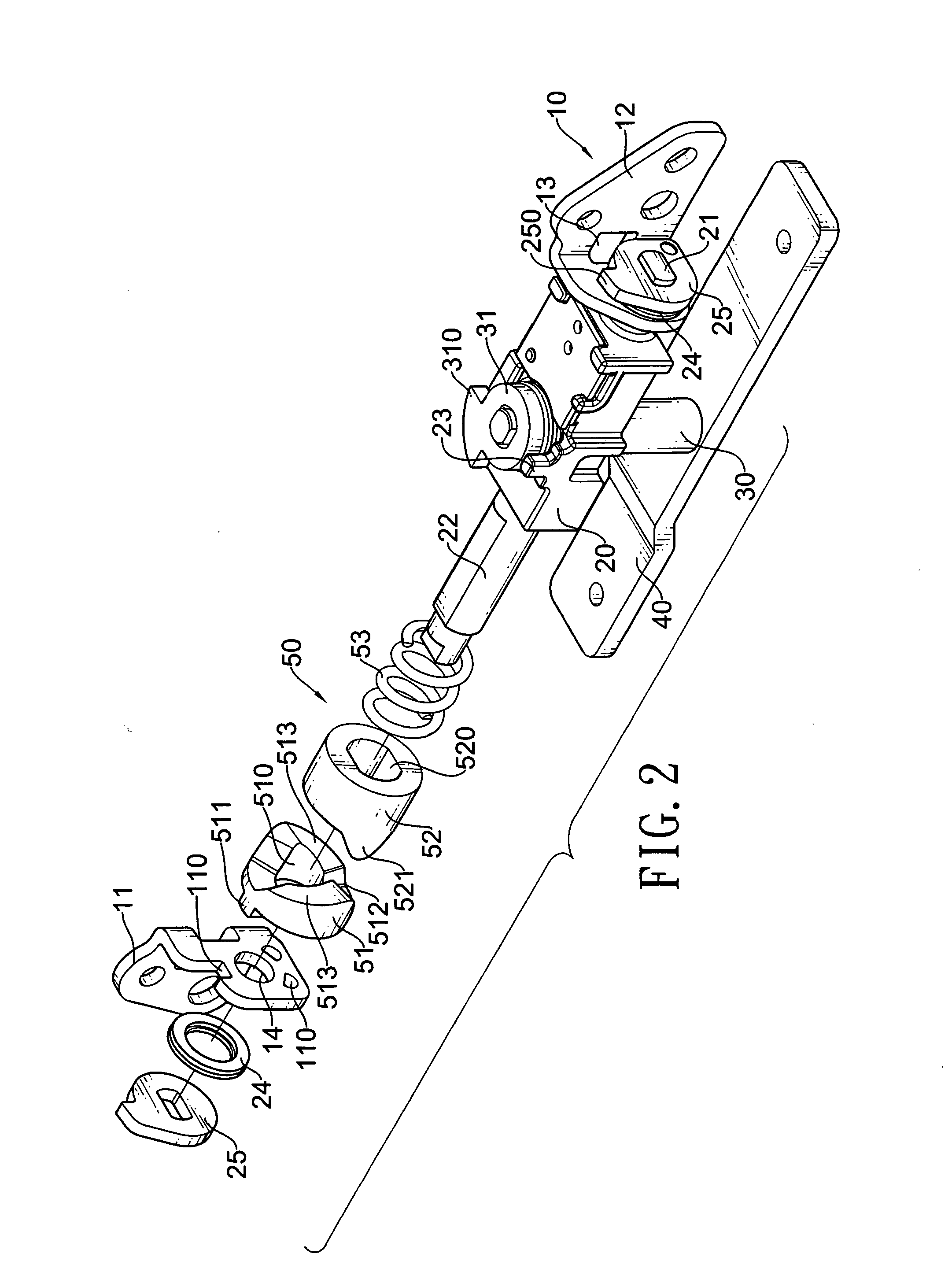
[0022]With reference to FIGS. 1, 2, 3 and 9, an automated hinge assembly in accordance with present invention comprises a moving leaf (40), a base (20), a driving member (50), a stationary leaf assembly (10) and two fastener assemblies.

[0023]The stationary leaf assembly (10) has a main stationary leaf (11) and a support stationary leaf (12). The stationary leaves (11, 12) are L shaped and each has an attachment end, a mounting end, a limiting notch (13) and a pintle hole (14). The limiting notch (13) is formed through the attachment end. The pintle hole (14) is defined through the mounting end. The main stationary leaf (11) further has at least one engaging mount (110) formed adjacent to the pintle hole (14).

[0024]With further reference to FIG. 6, the moving leaf (40) has an attachment portion and a shaft (30).

[0025]The shaft (30) is formed on and protrudes from the attachment portion of the moving leaf (40) and has a distal end and a limit (31). The limit (31) is mounted securely o...


PUM


Abstract

An automated hinge assembly has at least two leaves and a driving member. The leaves respectively connect securely to a cover and a body of a portable electronic device and are connected pivotally together. The driving member is mounted between the leaves and has a resilient element, a stationary bracket and a sliding bracket. The resilient element provides a force to automatically pivot a moving leaf from a stationary leaf. The stationary bracket has at least one inclined surface formed circularly around a central axis. The sliding bracket is pushed by the resilient element and has at least one protrusion corresponding to and abutting the inclined surface of the stationary bracket, thereby generating a torque to drive the leaf connected to the stationary bracket to rotate relative to another leaf.

Description

BACKGROUND OF THE INVENTION[0001]1. Field of the Invention[0002]The present invention relates to a hinge, and more particularly to an automated hinge assembly that can be mounted in a portable electronic device having a latched cover and a body, the cover opening when unlatched and is able to rotate relative to the body while unlatched.[0003]2. Description of Related Art[0004]Hinges are widely used in various portable electronic devices, such as laptops, mobile phones, hand-held cameras, digi-camcorders and the like. Generally, a portable electronic device comprises a body, a cover and at least one hinge. The cover may have a display mounted therein. The hinge pivotally connects the cover to the body and allows the cover to pivot relative to the body.[0005]However, conventional hinges require an external force to be applied to operate. Therefore, the cover must be turned by hand or tool to open the cover. This makes opening the cover inconvenient and time-consuming.[0006]To overcome...

Claims


Application Information

Patent Timeline
IPC IPC(8): E05D3/04E05D7/00E05D11/06
CPCE05D3/10E05D11/1078Y10T16/5453H04N5/2251Y10T16/53845E05Y2900/606
Inventor CHEN, CHIA-HSIANG
Owner SHIN ZU SHING
Why Eureka
Try Eureka