

Slide Fastener and a Top Stop for a Slide Fastener
a technology of slide fastener and top stop, which is applied in the direction of clothes buttons, haberdashery, etc., can solve the problems of compromising the fluid tightness of the fastener at the region of the top stop, and achieve the effect of preventing accidental opening, and quick and simple locking/unlocking action
- Summary
- Abstract
- Description
- Claims
- Application Information
AI Technical Summary
Benefits of technology
Problems solved by technology
Method used
Image

Examples
Embodiment Construction
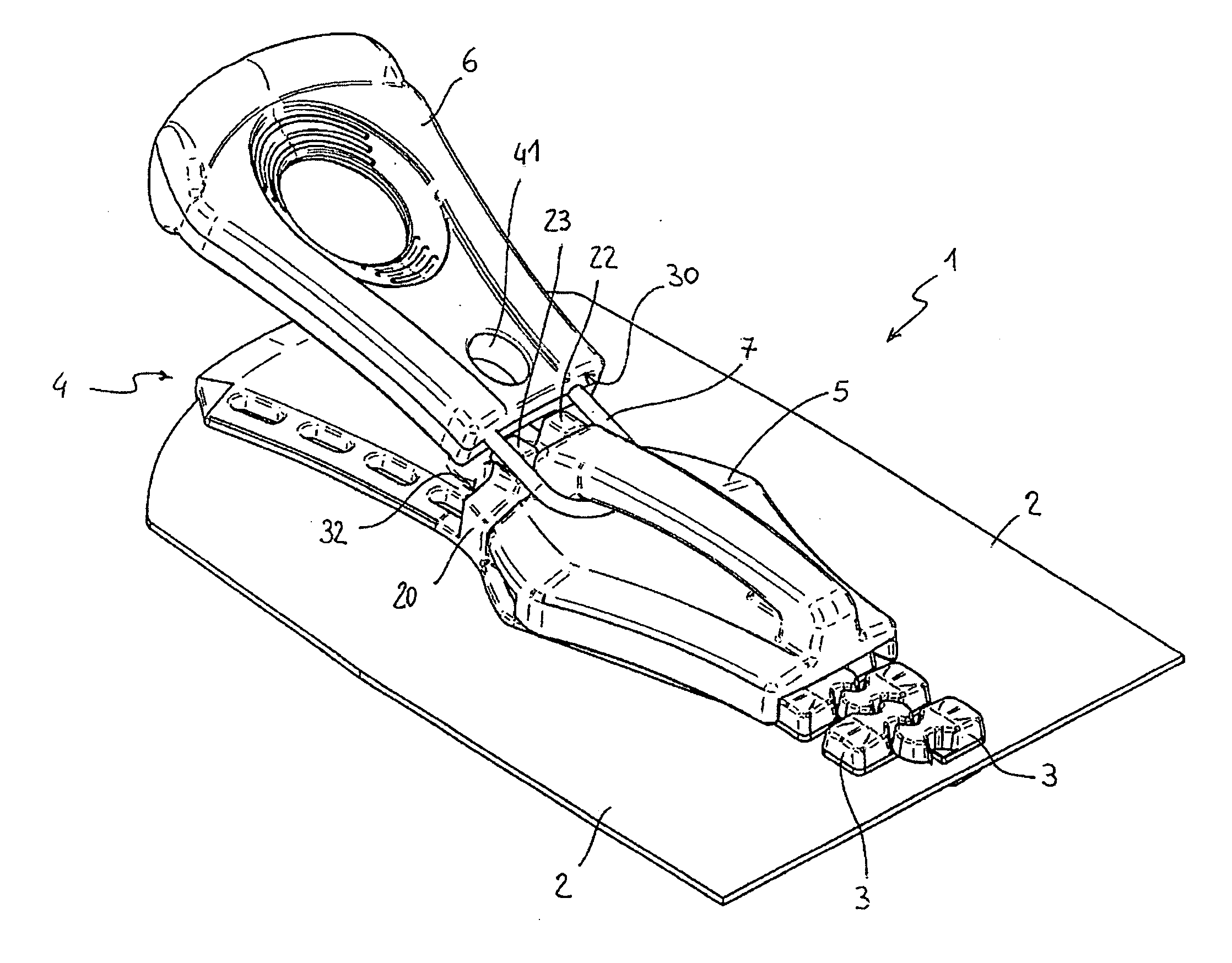
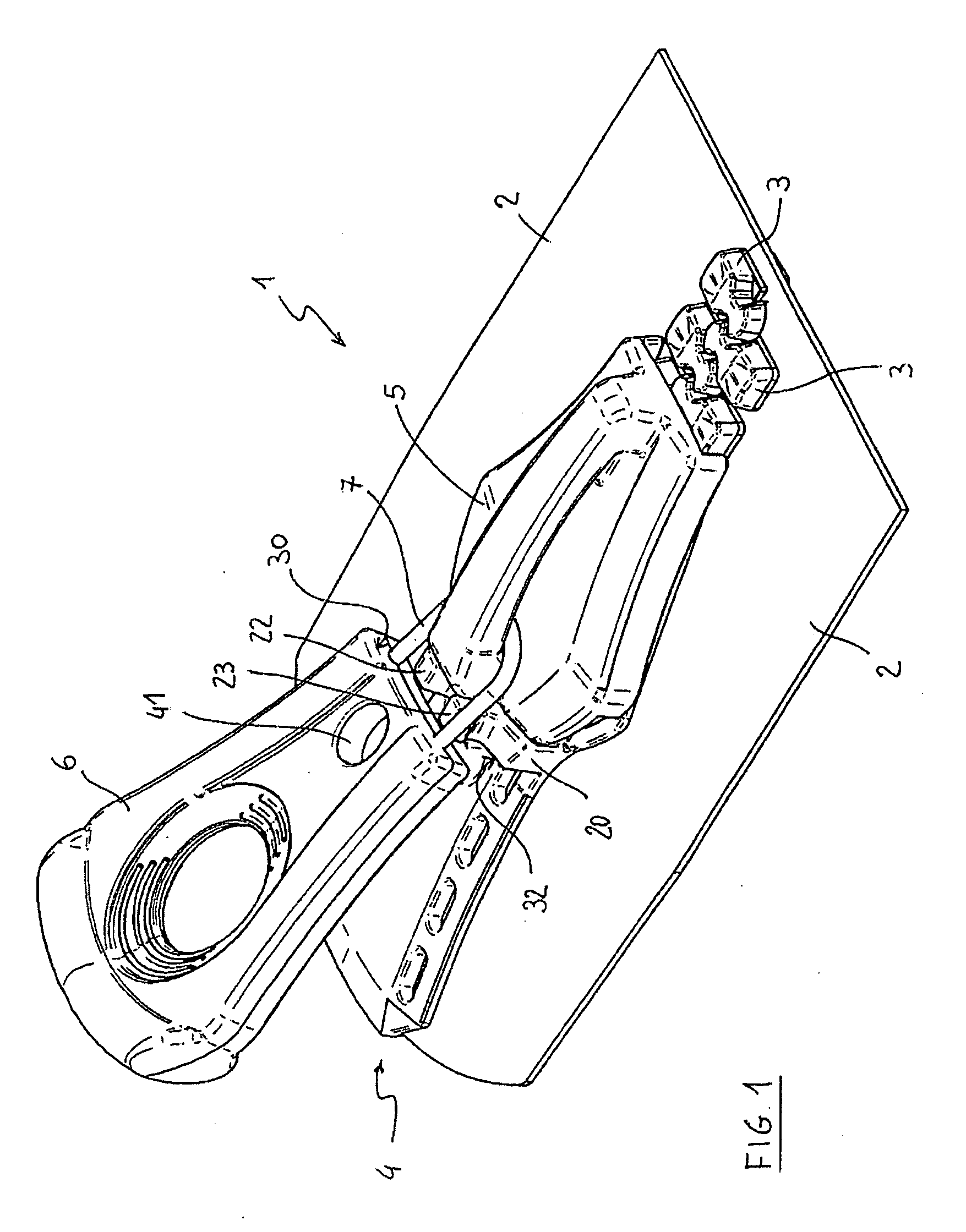
[0032]FIG. 1 shows a top portion of a slide fastener 1, in accordance with a preferred embodiment of the invention, comprising a pair of tapes 2, equipped with teeth 3, a top stop 4, and a slider 5 with a puller 6. The puller 6 is connected to the slider 5 by a ring 7.
[0033]The slider 5 is movable in a sliding direction, parallel to tapes 2, up to a closing position where the slide fastener 1 is fully closed, i.e. all teeth 3 are engaged and the slider 5 is in contact with the top stop 4. Said closing position is shown in FIG. 1.
[0034]Details of tapes 2 an teeth 3 can be according to known art and are not discussed in detail. For example, in a fluid-tight sliding fastener, tapes 2 are made of a textile core layer fully coated on both sides by a suitable waterproof layer and teeth 3 are injection-molded on tapes 2. The top stop 4, in a fluid-tight slide fastener, can also be injection-molded on tapes 2.
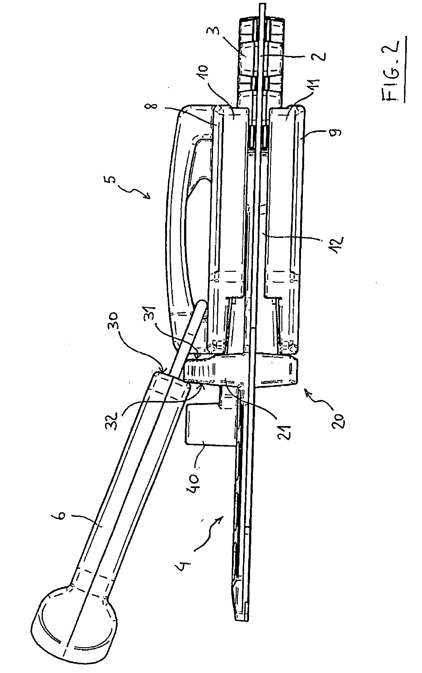
[0035]The slider 5 (FIG. 2) substantially comprises upper and lower blades 8, 9 wi...
PUM
 Abstract
Description
Claims
Application Information