
Circulation and drain system in a washing machine and a method thereof

Inactive Publication Date: 2009-09-17
SAMSUNG ELECTRONICS CO LTD
View PDF6 Cites 22 Cited by
  • Summary
  • Abstract
  • Description
  • Claims
  • Application Information

AI Technical Summary

Benefits of technology

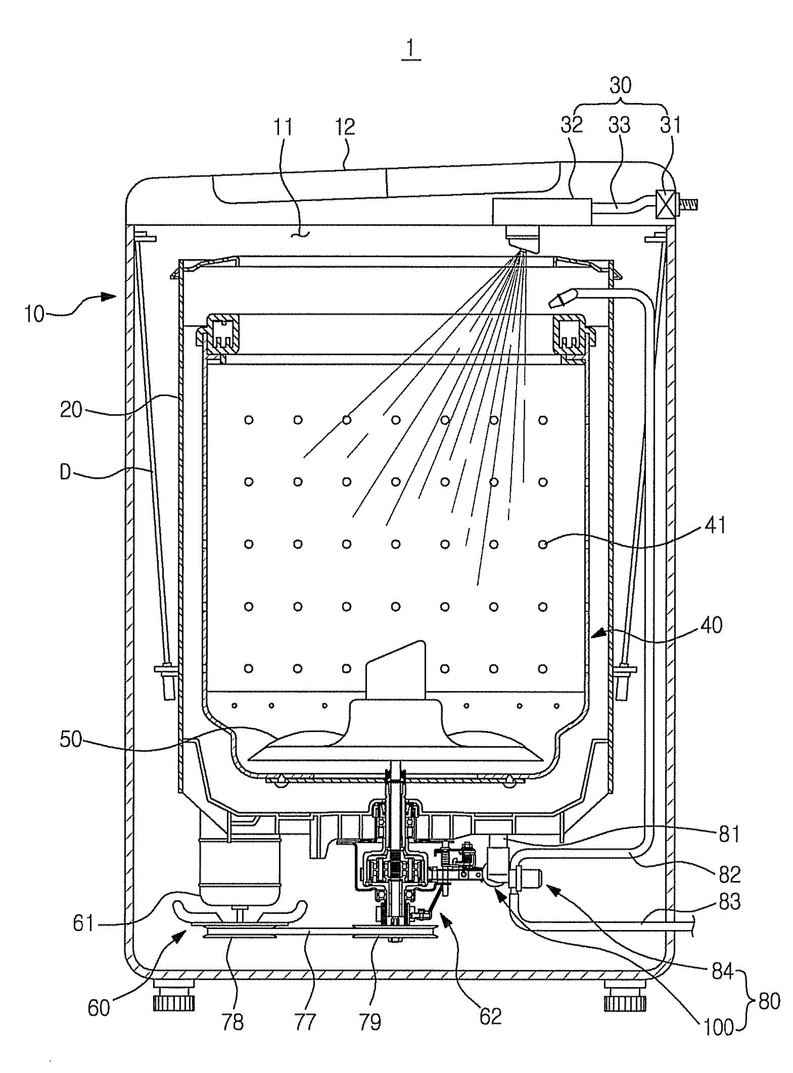
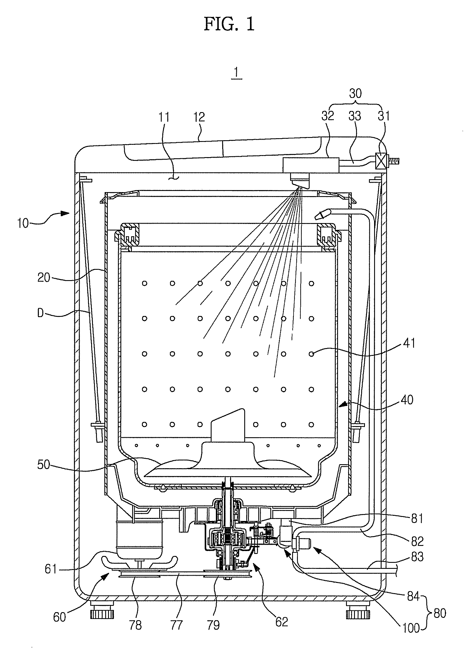
[0011]The present invention has been made in order to solve the above problems. It is an aspect of the invention to provide a washing machine having a simple structure, a low manufacturing cost and operational reliability by improving a circulation and drain structure of washing water.
[0030]In the washing machine according to the present invention, since the circulation line or the discharge line is opened and closed by the single reciprocating member, there are effects of simplifying the structure of the washing machine, reducing the manufacturing cost, and improving operational reliability.

Problems solved by technology

Generally, the washing machine having the circulation structure includes an additional circulation pump for circulation of washing water in addition to a drain pump for drain of washing water which causes problems of complicated inner structure and increase in the manufacturing cost.
However, in the washing machine disclosed in Korean Patent Laid-open Publication No. 10-2007-059433, since the valves having the same number as the drain paths are necessary to open and close the plurality of drain paths, there are still problems of complicating an inner structure and increasing the manufacturing cost.
Thus, there are problems of complicating the control and increasing the possibility of malfunctioning valves.

Method used


Image

  • Circulation and drain system in a washing machine and a method thereof
  • Circulation and drain system in a washing machine and a method thereof
  • Circulation and drain system in a washing machine and a method thereof

Examples


first embodiment

[0073]Hereinafter, another embodiment of the present invention will be described in detail with reference to the accompanying drawings. However, the description of the same or corresponding components as those described in the first embodiment is omitted.

second embodiment

[0074]FIGS. 5A and 5B illustrate cross-sectional views of a flow path switching structure according to the present invention.

[0075]A flow path switching device 200 according to the second embodiment includes a hollow pipe 210, a reciprocating member 220 which is slidably disposed in a hollow portion of the hollow pipe 210, a rod 223 having one end coupled to the reciprocating member 220 and the other end coupled to a drawing motor (not shown), a return spring 250 in which the rod 223 is inserted to elastically support the reciprocating member 220, and a sealing member 260 which prevents outflow of the washing water.

[0076]Particularly, the sealing member 260 according to the second embodiment is formed in an annular shape on the front and rear of an outlet 222 of an inner flow path 221. Accordingly, the flow path switching device 200 may have a compact configuration. Of course, the sealing member 260 may be formed in a circular shape to surround the outlet 222 of the inner flow path ...

third embodiment

[0078]FIGS. 6A and 6B illustrate cross-sectional views of a flow path switching structure according to the present invention.

[0079]In a flow path switching device 300 according to the third embodiment, when a reciprocating member 320 is positioned at a first position (see FIG. 6A), a suction port 311 communicates with a first drain port 312 through an inner flow path 321 of the reciprocating member 320. When the reciprocating member 320 is positioned at a second position (see FIG. 6B), in the same way, the suction port 311 communicates with a second drain port 313 through the inner flow path 321 of the reciprocating member 320.

[0080]FIGS. 7A and 7B illustrate cross-sectional views of a flow path switching structure according to a fourth embodiment of the present invention. The washing machine according to the fourth embodiment includes a solenoid driving unit 470 at one side of the reciprocating member to operate a flow path switching device 400. As in the fourth embodiment, the dri...


PUM


Abstract

A washing machine having an improved structure in circulation and drain of washing water are disclosed. The washing machine includes a main body, a water tub which is disposed in the main body, a drain line in which washing water drained from the water tub flows, a circulation line in which washing water returning to the water tub flows, a discharge line in which washing water discharged out of the main body flows, a pump which flows the washing water such that the washing water drained from the water tub returns to the water tub or is discharged out of the main body, a flow path switching device having a single reciprocating member which opens and closes the circulation line or the discharge line, and an operating unit which operates the flow path switching device.

Description

CROSS-REFERENCE TO RELATED APPLICATION[0001]This application claims the benefit of Korean Patent Application No. 2008-0023857, filed on Mar. 14, 2008 in the Korean Intellectual Property Office, the disclosure of which is incorporated herein by reference.BACKGROUND OF THE INVENTION[0002]1. Field of the Invention[0003]The present invention relates to a washing machine, and more particularly to a washing machine having an improved structure in circulation and drain of washing water.[0004]2. Description of the Related Art[0005]Recently, a washing machine having a washing water circulation structure, in which washing water is pumped out of a water tub and is restored to the water tub, is being developed and manufactured to improve washing and rinsing performance of the washing machine.[0006]Generally, the washing machine having the circulation structure includes an additional circulation pump for circulation of washing water in addition to a drain pump for drain of washing water which ca...

Claims


Application Information

Patent Timeline
IPC IPC(8): D06F39/08F04B7/00
CPCD06F39/083D06F2103/14D06F2105/06
Inventor CHUNG, SEUNG HWANAHN, SEUNG KWUN
Owner SAMSUNG ELECTRONICS CO LTD
Features
  • Generate Ideas
  • Intellectual Property
  • Life Sciences
  • Materials
  • Tech Scout
  • Unparalleled Data Quality
  • Higher Quality Content
  • 60% Fewer Hallucinations
Learn More