Latch for a motor-vehicle headrest

Active Publication Date: 2009-09-17
GRAMMER AG
View PDF10 Cites 2 Cited by
  • Summary
  • Abstract
  • Description
  • Claims
  • Application Information

AI Technical Summary

Benefits of technology

[0013]The advantage of the invention is that the latch has a very low size, in particular when the levers are designed as flat, plate-shaped elements. Furthermore, the device can be readily manufactured.
[0014]As a result of the arrangement of the latch formation and of the contact region on the locking lever the holding force to be applied by the actuator can be low. In addition, as a result of the design of the locking lever a flexible arrangement of the elements of the latch is possible in a receiving space, for example a upholstered support of a head support.
[0015]The locking lever can be arranged in the retaining position of the latch in such a manner close to a dead-center position in which the entire force transferred onto the locking lever is carried by the pivot support of the locking lever so that only a low torque is produced in the locking lever.
[0016]Thus, t

Problems solved by technology

This state of the art has the disadvantage of a relatively large space requirement.
This system has a ve

Method used


Image

  • Latch for a motor-vehicle headrest
  • Latch for a motor-vehicle headrest
  • Latch for a motor-vehicle headrest

Examples


Example

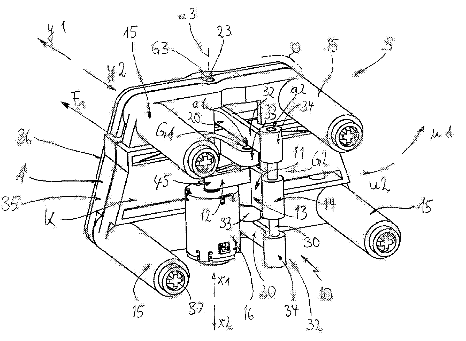
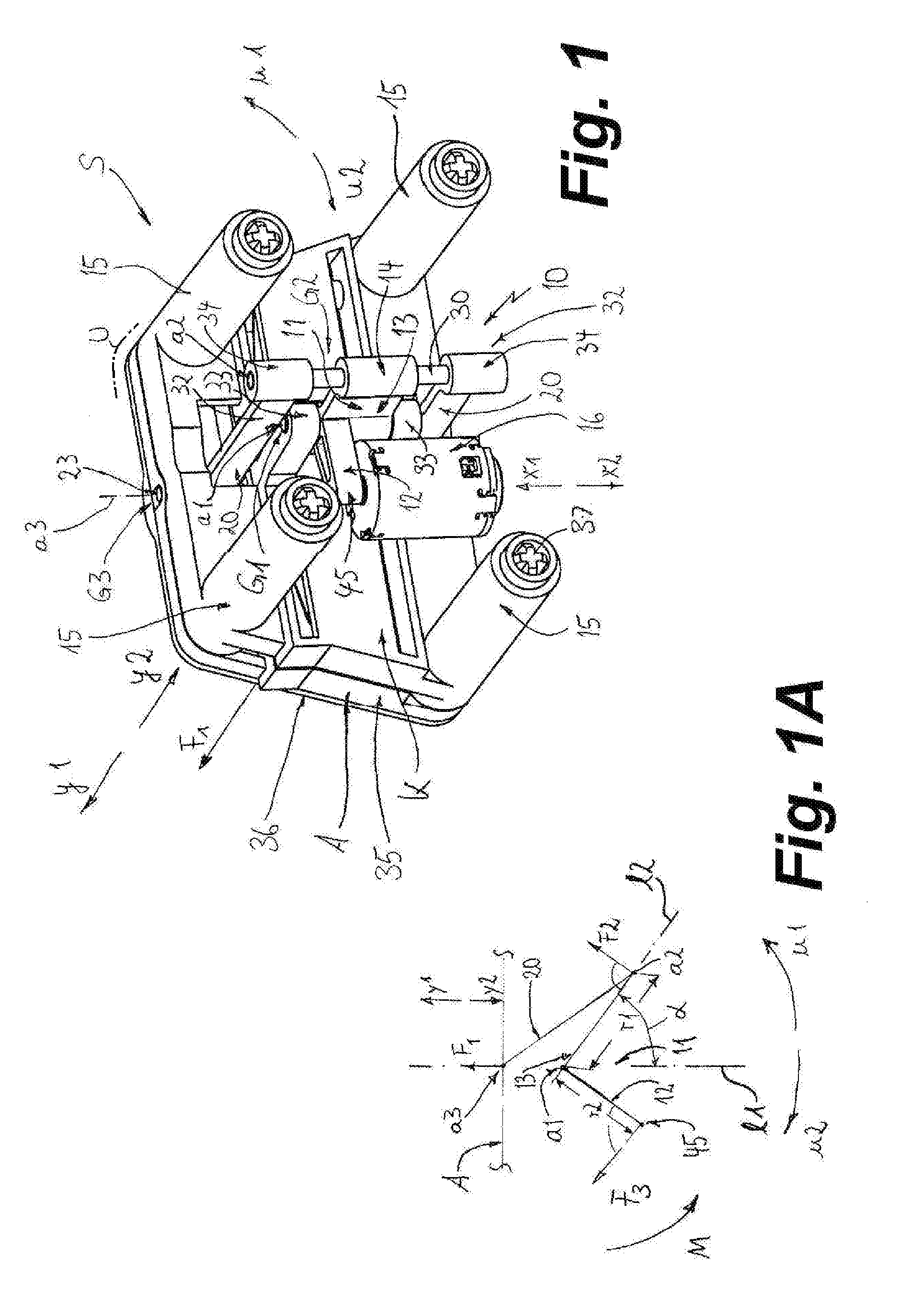
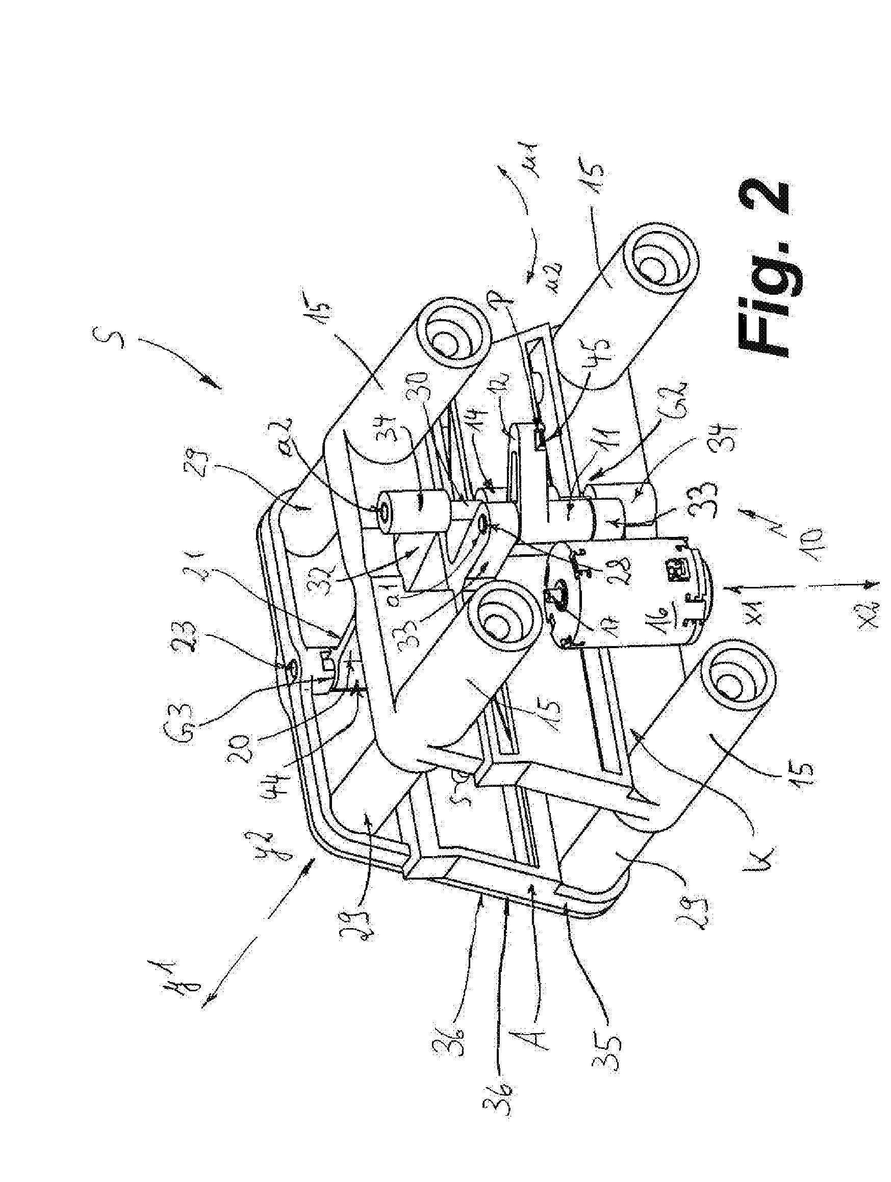
[0038]As seen in FIG. 1 a motor-vehicle headrest support S provided with padding or upholstery indicated schematically at U has a latch 10. The support S has a base K as well as a part A. The part A can move relative to the part K in a horizontal straight line in the directions y1 and y2 by means of posts 29 sliding in sleeves 15 formed on the base K. The part A can be shifted out of the starting or rest position shown in FIG. 1 into an advanced or collision-protection position shown in FIG. 2 by springs shown schematically in FIG. 2 at S, in which advanced position the part A is spaced forward of the base K and close to the head of the seat passenger. The part A is held according to FIG. 1 by the latch 10 against the spring force of the springs S in the rest position.

[0039]The latch 10 has a locking lever 11 that is held on support arms 33 at a pivot G1 in such a manner that it can rotate about a lever axis a1 fixed to the base K. The lever axis a1 is formed by a pin 28 carried in ...


PUM


Abstract

A latch secures an element such as a motor-vehicle headrest for movement relative to a support between a rest position and an advanced position. A pivotal lever can hold the element in the rest position. A spring pushes the element into the advanced position and presses it against the lever so as to apply a torque to the lever that presses a latch formation on the lever against a retractile latch part of an actuator. If the actuator retracts the part, the lever is released and the lever can pivot to allow the spring to move the element into the advanced position.

Description

FIELD OF THE INVENTION[0001]The present invention relates to a motor-vehicle headrest. More particularly this invention concerns a latch for maintaining an active motor-vehicle headrest in its rest position.BACKGROUND OF THE INVENTION[0002]Such a latch is known from German 198 30 407 of Bender that serves to lock and unlock a roll bar that is part of an electromechanical roll-protection system. The latch has a two-armed lever that can move between a retaining position that locks a holder and one that releases the holder. One arm of the two-armed lever reaches around the holder in a retaining position and prevents movement of the roll bar into a crash-protection position. A spring urges the lever into a freeing position. A second lever is also constructed with two arms, one of which cooperates with the first lever and prevents it from pivoting into the freeing position. The second lever can be pivoted by an actuator, during which it loses contact with the first lever so that the latt...

Claims


Application Information

Patent Timeline
IPC IPC(8): E05C3/06B60N2/90
CPCB60N2/442B60N2/4885B60N2/4864B60N2/888B60N2/919B60N2/865Y10T292/108
Inventor WALLINGER, THOMASSCHENKL, MANFREDMEIER, JOSEFLUBER, EBERHARD
Owner GRAMMER AG
Why Eureka
Try Eureka