Multiple band pass liquid crystal tunable filter

a liquid crystal filter and multi-band technology, applied in the field of optical filters, can solve the problems of low peak transmission value of optical filters, conventional fixed-wavelength optical filters, etc., and achieve the effect of improving the transmission valu

Active Publication Date: 2021-06-29
LEICA INSTR SINGAPORE PTE
View PDF11 Cites 0 Cited by
  • Summary
  • Abstract
  • Description
  • Claims
  • Application Information

AI Technical Summary

Benefits of technology

[0033]The above-mentioned embodiments of the inventive optical filter therefore yield further advantages over prior art optical filters as they allow real time imaging of multiple spectral bands instead of one spectral band of the prior art. This, in turn, results in an accordingly faster scanning speed combined with a better through-put efficiency, i.e. lower losses and lower costs and size.

Problems solved by technology

Independent of the configuration used, optical filters of the art show the disadvantage of a low peak transmission value, especially in comparison to conventional fixed-wavelength optical filters.

Method used


Image

  • Multiple band pass liquid crystal tunable filter
  • Multiple band pass liquid crystal tunable filter
  • Multiple band pass liquid crystal tunable filter

Examples


Embodiment Construction

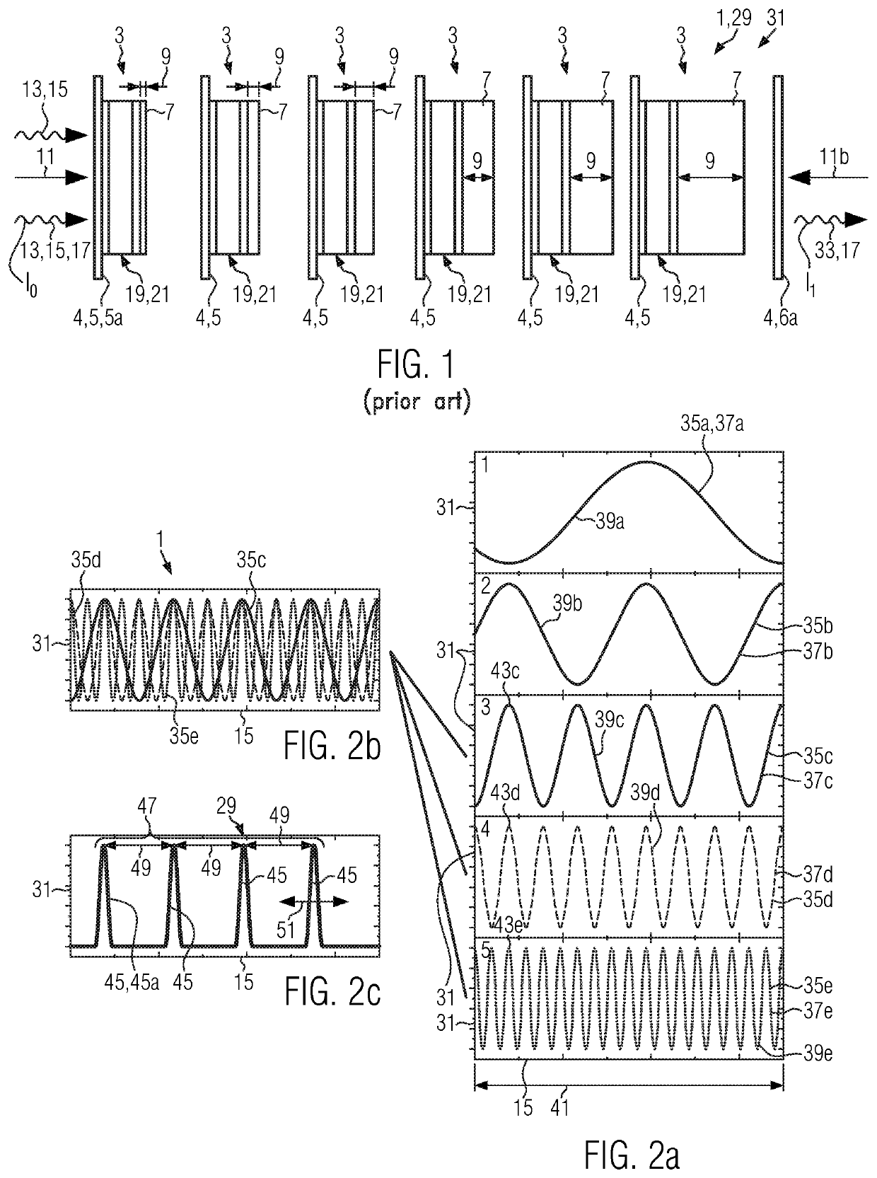
[0066]FIG. 1 shows a schematic working principle of an optical filter 1 of the art. The optical filter 1 comprises, six optical filter stages 3 in the embodiment shown, wherein each of the optical filter stages 3 comprises an entrance polarizing element 5 and one constant retarding element 7 which yields an increasing thickness 9 from the left optical filter stage to the optical filter stage 3 at the right side of FIG. 1.

[0067]Furthermore, each optical filter stage 3 comprises a variable retarding element 19 which is embodied as a liquid crystal element 21. Each liquid crystal element 21 comprises a liquid crystal 23 provided in between two glass plates 25 provided with optically transmissive electrodes 27. The liquid crystal 23, the glass plates 25 and electrically transmissive electrodes 27 are indicated by reference numerals only for the left optical filter stage 3.

[0068]Each optical filter stage 3 comprises two polarizing elements which are oriented such that linearly polarized ...


PUM

PropertyMeasurementUnit
transmissionaaaaaaaaaa
color codingaaaaaaaaaa
wavelength rangeaaaaaaaaaa

Abstract

The invention relates to an optical filter (1) for transmitting light (13) of a pass wavelength (17), comprising at least two optical filter stages (3) arranged along a transmission direction (11), along which the light (13) of the pass wavelength (17) is transmitted through the optical filter (1), wherein each of the at least two optical filter stages (3) comprises at least one entrance polarizing element (5) and at least one constant retarding element (7). The invention further relates to a camera (53) for simultaneously capturing at least two images, wherein each image is limited to light (13) in a limited spectral band (44) and to a multi-spectral imaging system (87) and an illumination system (73) applying the inventive optical filter (1). Solutions of the art have low peak transmission values and may furthermore only provide monochrome images in real time. The present invention improves optical filters (1) of the art by each of the at least two optical filter stages (3) comprising a periodic transmission characteristic (35) that extends over a working wavelength range (41), wherein each transmission characteristic (35) comprises at least two peaks (43c-43e), which each overlap at least one peak (43c-43d) of each of the other transmission characteristics (35) and wherein an overall transmission characteristic (29) of the optical filter (1) comprises at least two spectral passbands (45) that are spectrally separated from each other. The inventive camera (53), multi-spectral imaging system (87) and inventive illumination system (73) apply an optical filter (1) according to the invention.

Description

CROSS REFERENCE TO RELATED APPLICATIONS[0001]This application claims priority of European patent application number 17166085.5 filed Apr. 11, 2017, the entire disclosure of which is incorporated by reference herein.FIELD OF THE INVENTION[0002]The invention relates to an optical filter for transmitting light of a pass wavelength comprising at least two optical filter stages arranged along a transmission direction, along which the light of the pass wavelength is transmitted through the optical filter, wherein each of the at least two optical filter stages comprises at least one entrance polarizing element and at least one constant retarding element.[0003]The invention further relates to a camera for simultaneously capturing at least two images, wherein each image is limited to light in a limited spectral band, a multi-spectral imaging system and an illumination system.BACKGROUND OF THE INVENTION[0004]Optical filters based on a multitude of filter stages which each comprise birefringen...

Claims


Application Information

Patent Timeline
Patent Type & Authority Patents(United States)
IPC IPC(8): G02B5/30G02B27/28H04N5/225G01J3/28G01J3/36G02F1/1335G01N21/25G01N21/31G03B11/00
CPCG02B27/28G01J3/2803G01J3/2823G01J3/36G02B5/30G02B27/288H04N5/2254G01N21/255G01N21/31G02F1/133514G02B5/20G02F1/1313G03B11/00G01J2003/1213G01J2003/2806G01J3/0205G01J3/32H04N23/55
Inventor THEMELIS, GEORGE
Owner LEICA INSTR SINGAPORE PTE
Why Eureka
Try Eureka