
Vehicle power supply device

Active Publication Date: 2009-09-17
SUBARU CORP
View PDF7 Cites 50 Cited by
  • Summary
  • Abstract
  • Description
  • Claims
  • Application Information

AI Technical Summary

Benefits of technology

[0012]According to the vehicle power supply device of the present invention, deterioration of the c

Problems solved by technology

However, increases in the capacity of the capacitor lead to increases in the amount of power that is lost by discharging the capacitor when the IG SW is switched OFF and the amount of time required for precharging before the main relay is switched ON.
Hence, particularly when the vehicle is driven for a short ti

Method used


Image

  • Vehicle power supply device
  • Vehicle power supply device
  • Vehicle power supply device

Examples


Embodiment Construction

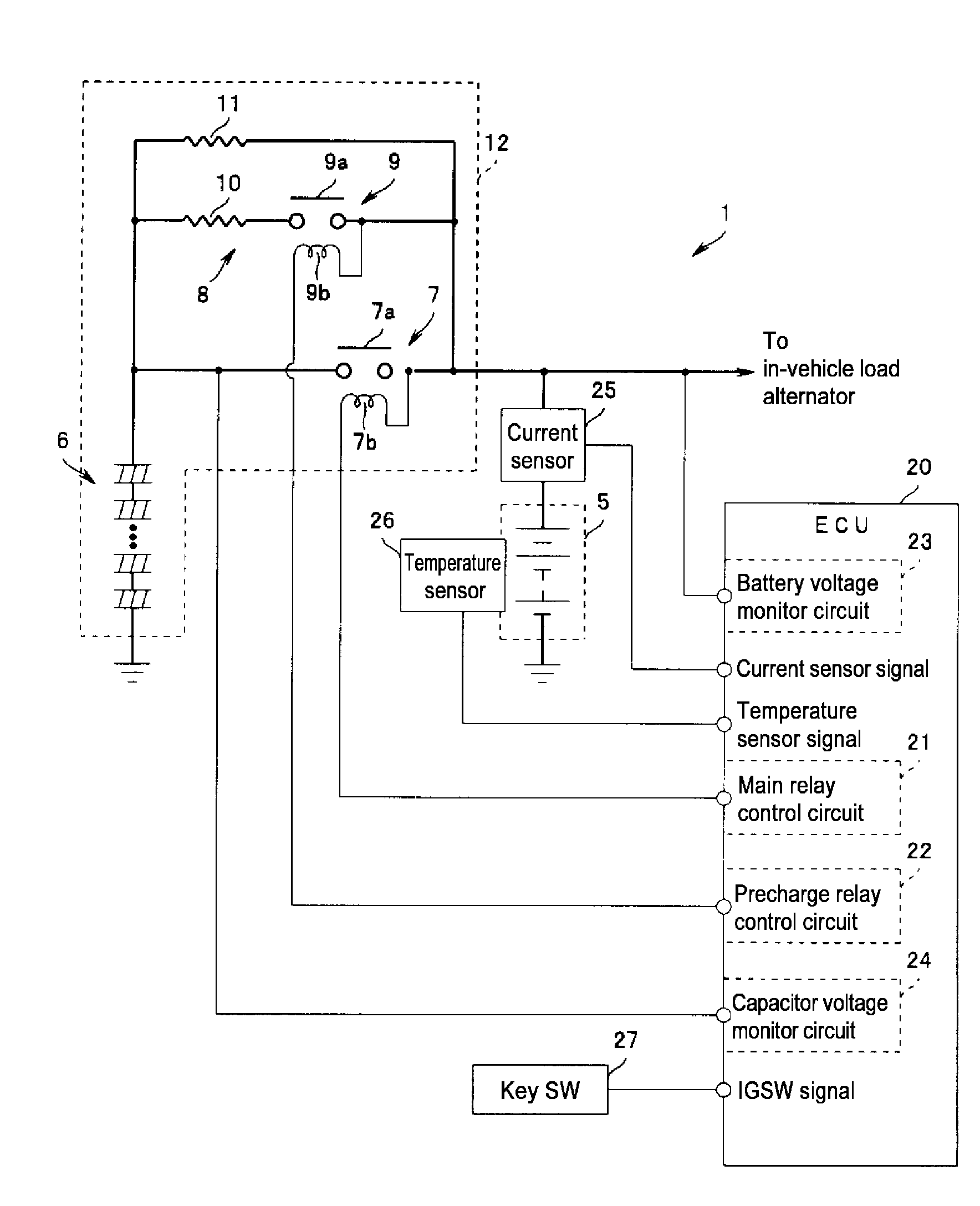
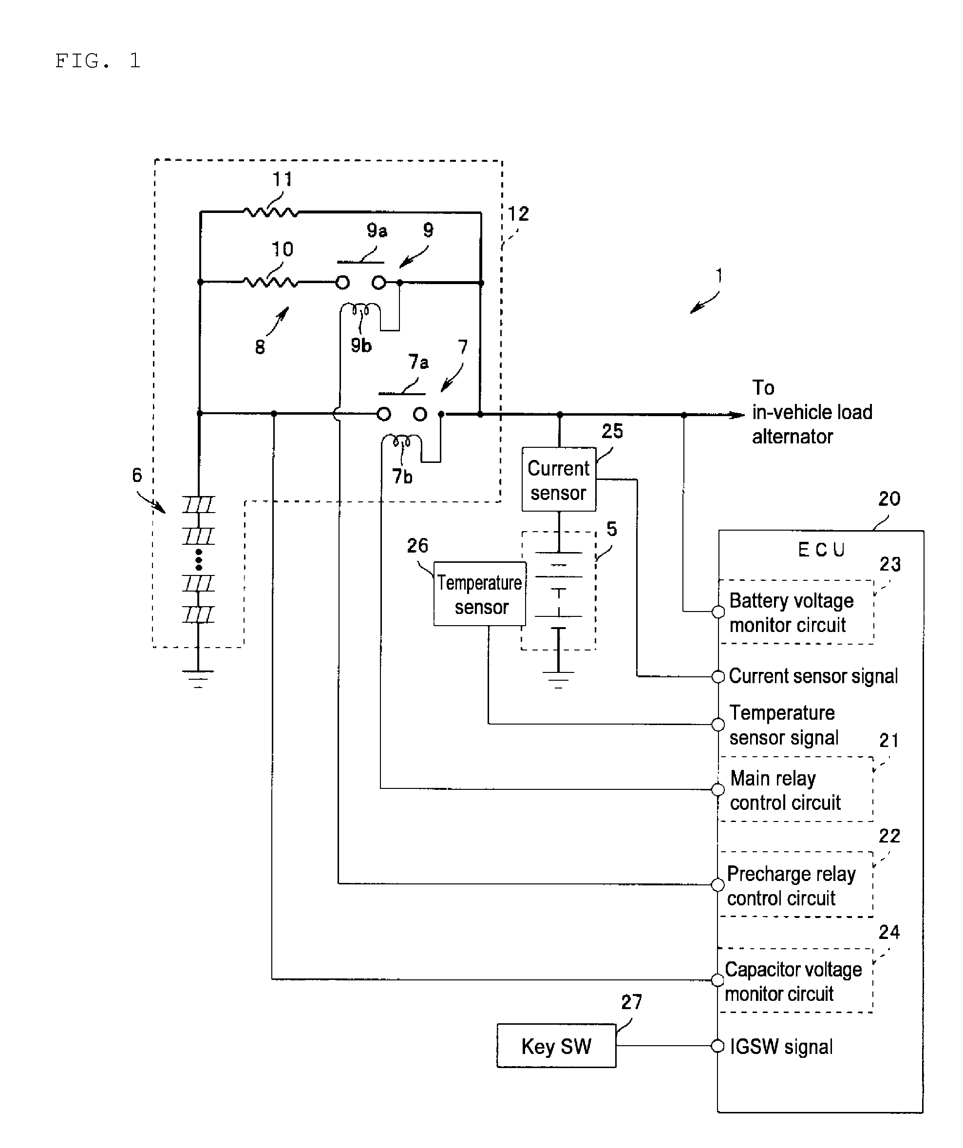
[0021]An embodiment of the present invention will be described below with reference to the drawings. A vehicle power supply device 1 shown in FIG. 1 is mainly constituted by a battery 5 serving as a secondary battery, and a capacitor 6 that is connected parallel to the battery 5 via a main relay 7, for example.

[0022]The battery 5 is a 12V battery constituted by a lead storage battery or the like, which is connected to in-vehicle loads (not shown) such as various types of accessories to be capable of supplying power thereto, and to which an alternator (not shown) capable of regenerating energy during vehicle deceleration is connected.

[0023]The capacitor 6 is mainly constituted by a cell group comprising a plurality of electric double layer capacitor cells, lithium ion capacitor (LIC) cells, or the like, for example. From the viewpoint of realizing a long lifespan in the capacitor 6, LIC cells, the lifespan of which is unlikely to decrease even when the cells are maintained in a charg...


PUM


Abstract

The present invention provides a vehicle power supply device that is capable of suppressing deterioration of a capacitor, shortening a precharging time, and suppressing power loss. An ECU estimates a polarization condition of a battery after a key has been switched OFF (IG SW_OFF), and opens a main relay after determining that the polarization condition of the battery has been eliminated. Thus, a voltage difference between a battery voltage and a capacitor voltage when the main relay is subsequently reconnected can be reduced. Hence, even when the capacity of the capacitor is increased, the time required for precharging can be shortened, and energy regeneration and so on can be realized efficiently within a short time period after switching the key ON. In this case, a situation in which the post-release capacitor voltage is maintained at an unnecessarily high level can be prevented even when charging polarization occurs in the battery, and as a result, deterioration of the capacitor can be suppressed.

Description

CROSS-REFERENCE TO RELATED APPLICATION[0001]The present application claims priority under 35 U.S.C. §119 to Japanese Patent Application No. 2008-063156, filed on Mar. 12, 2008, and which is hereby incorporated by reference herein it its entirety.BACKGROUND OF THE INVENTION[0002]1. Field of the Invention[0003]The present invention relates to a vehicle power supply device in which a capacitor is disposed parallel to a secondary battery.[0004]2. Description of the Related Art[0005]It has been proposed in the related art that a capacitor such as an electrolytic capacitor or an electric double layer capacitor be disposed parallel to a secondary battery such as a lead battery in a power supply device for various types of vehicles such as a gasoline vehicle, a diesel vehicle, a hybrid vehicle, and an electric automobile. When this type of power supply device is installed in an electric automobile or the like, for example, energy generated during vehicle deceleration can be regenerated effi...

Claims


Application Information

Patent Timeline
IPC IPC(8): H02H7/18
CPCF02N11/0866H02J7/1423Y02T10/7022Y02T10/7005H02J7/345Y02T10/70
Inventor MIYAMA, SYUJIYASUOKA, KENTARO
Owner SUBARU CORP
Learn More