Projection display system with varying light source

a technology of projection display and light source, applied in the field of projection display system with varying light source, can solve the problems of limitation and difficulty in providing high-quality images display, adverse effects on image quality, limitation of display quality, etc., and achieve the effect of reducing heat generation and electric power consumption

Inactive Publication Date: 2009-09-17
SILICON QUEST KABUSHIKI KAISHA +1
View PDF16 Cites 3 Cited by
  • Summary
  • Abstract
  • Description
  • Claims
  • Application Information

AI Technical Summary

Benefits of technology

[0014]It is an object of the present invention to provide a technology that can realize the reduction of heat generation and electric power consumption in a light source in a projection apparatus comprising a spatial light modulator.

Problems solved by technology

Even though there are significant advances made in recent years on the technologies of implementing electromechanical micro-mirror devices as spatial light modulator, there are still limitations and difficulties when employed to provide high quality images display.
Specifically, when the display images are digitally controlled, the image qualities are adversely affected due to the fact that the image is not displayed with sufficient number of gray scales.
The on-and-off states of micro-mirror control scheme as that implemented in the U.S. Pat. No. 5,214,420 and by most of the conventional display system imposes a limitation on the quality of the display.
Specifically, when applying conventional configuration of control circuit has a limitation that the gray scale of conventional system (PWM between ON and OFF states) is limited by the LSB (least significant bit, or the least pulse width).
Due to the On-Off states implemented in the conventional systems, there is no way to provide shorter pulse width than LSB.
The limited gray scales lead to degradations of image display.
However, these types of light sources are poor in performing high-speed switching between ON and OFF.
Accordingly, a light source is usually controlled to be always in an ON state during the use of the projection apparatus, which causes a large mount of heat and waste of light and electric power.
However, if the improvement of the gray scale performance is to be achieved only through the control of the spatial light modulator, the improvement would be only to a limited level.

Method used


Image

  • Projection display system with varying light source
  • Projection display system with varying light source
  • Projection display system with varying light source

Examples


embodiment 1-1

Preferred Embodiment 1-1

[0115]A preferred embodiment 1-1 of the present invention relates to a mirror device configured to arranging a plurality of deflectable mirrors in array and further specifically to a method for regulating the deflection angle of a mirror.

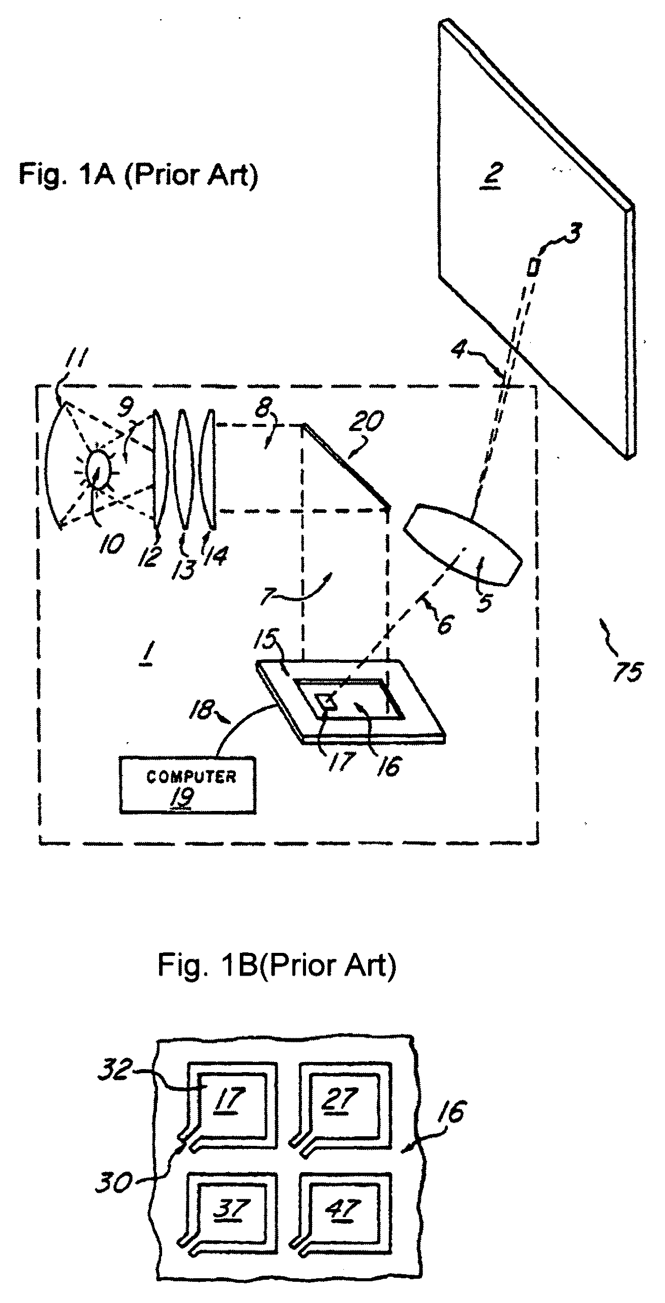
[0116]FIG. 1E is an illustrative diagram for showing etendue by exemplifying the case of using a discharge lamp light source and projecting an image by way of an optical device.

[Outline of the Device]

[0117]The first is a description of a mirror device.

[0118]Projection apparatuses each generally using a spatial light modulator, such as a transmissive liquid crystal, a reflective liquid crystal, a mirror array and the like, are widely known.

[0119]A spatial light modulator is formed as a two-dimensional array arranging from tens of thousands to millions of miniature modulation elements, with the individual elements enlarged and displayed, as the individual pixels corresponding to an image to be displayed, onto a screen by way of...

embodiment 3-1

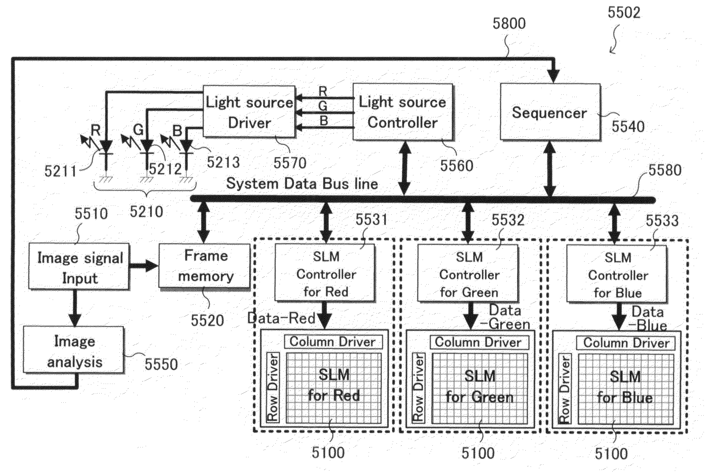
[0263]The embodiment shown in FIG. 8A makes it possible to continuously adjust the intensity of emission of the variable light source 5210 while the spatial light modulator 5100 is driven, that is, during the displaying of an image onto the screen 5900, and change the brightness of a pixel to be displayed, thereby enabling a control of the gray scale characteristic of the display video image. Further, the present embodiment is configured to adjust the emission intensity of the variable light source 5210 using a drive signal used for driving the spatial light modulator 5100, eliminating an extraneous emission of the variable light source 5210, thereby making it possible to suppress the heat therefrom and the power consumption thereof.

embodiment 3-2

[0264]FIG. 16A exemplifies an example of the waveform of a mirror control profile 6720 that is a control signal output from a SLM controller 5530 to a spatial light modulator 5100 and an example of the waveform of a light source pulse pattern 6801 generated by a light source control unit 5560 from a light source profile control signal 5800 corresponding to the aforementioned mirror control profile 6720.

[0265]In this case, one frame of the mirror control profile 6720 is constituted by the combination of a mirror ON / OFF control 6721 on the frame head side and a mirror oscillation control 6722 on the tail end side and is used for controlling the tilting operation of the mirror 5112 corresponding to the gray scale of the present frame.

[0266]That is, the mirror ON / OFF control 6721 controls the mirror 5112 under either of the ON state and OFF state, and the mirror oscillation control 6722 controls the mirror 5112 under an oscillation state in which it oscillates between the ON state and O...


PUM


Abstract

The present invention provides a projection apparatus, comprising: a light source for emitting illumination light; at least one spatial light modulator with a plurality of movable mirrors corresponding to pixels to be displayed, for performing a modulation of the illumination light through operation of the movable mirrors; a light source control unit performing a modulation control of the light source; and a spatial light modulator control unit generating, from an input image signal, a control signal for driving the spatial light modulator, wherein: the light source control unit adjusts a pulse emission frequency of an emission pulse of the illumination light emitted from the light source while corresponding to an oscillation frequency of the movable mirrors.

Description

BACKGROUND OF THE INVENTION[0001]1. Field of the Invention[0002]The present invention relates to a technology that ca advantageously applied to a projection apparatus or the like having a spatial light modulator.[0003]2. Description of the Related Art[0004]Even though there are significant advances made in recent years on the technologies of implementing electromechanical micro-mirror devices as spatial light modulator, there are still limitations and difficulties when employed to provide high quality images display. Specifically, when the display images are digitally controlled, the image qualities are adversely affected due to the fact that the image is not displayed with sufficient number of gray scales.[0005]Electromechanical micro-mirror devices have drawn considerable interest because of their application as spatial light modulators (SLMs). A spatial light modulator requires an array of a relatively large number of micro-mirror devices. In general, the number of devices requir...

Claims


Application Information

Patent Timeline
Patent Type & Authority Applications(United States)
IPC IPC(8): G02B26/02
CPCG02B26/0841G09G3/2011H04N9/3197H04N9/312H04N9/3155G09G3/346
Inventor SHIRAI, AKIRANISHINO, HIROKAZUHORIKAWA, YOSHIAKIISHII, FUSAO
Owner SILICON QUEST KABUSHIKI KAISHA
Why Eureka
Try Eureka