
Waterproof Ventilated Display Enclosure

a ventilated enclosure and enclosure technology, applied in the direction of cooling/ventilation/heating modifications, cabinets, casings/cabinets/drawer details, etc., can solve the problems of inability to solve the problem of effectively sealing the equipment from water, high cost and noise of ducted air conditioning, and the inability to use such equipment outdoors. the effect of increasing the cost of us

Inactive Publication Date: 2009-09-17
PREMIER MOUNTS
View PDF16 Cites 76 Cited by
  • Summary
  • Abstract
  • Description
  • Claims
  • Application Information

AI Technical Summary

Benefits of technology

[0020]A further aspect of the disclosure is a method of protecting equipment from rain while providing ventilation therefore, comprising the steps of: providing an enclosure for the equipment which is generally fluid impervious except for defined openings in the top and bottom thereof; providing a first liquid passageway which connects the openings on the top and bottom; providing a second air passageway which connects at least some of the openings in the top to the space containing the equipment, said air passageway following a path which at least partway along its path, forces the air to flow in a direction against the force of gravity; providing a barrier between the two pathways so that fluid, which must follow the path of gravity will be prevented from entering the space provided for the equipment, while said space is ventilated through the air passageway.

Problems solved by technology

The problem is not new to flat screens however, CRTs have similar problems and there has been a long felt need to find a relatively inexpensive solution to these problems.
Solutions which solve waterproofing by effectively sealing the equipment from water are unacceptable as they do not solve the heat management problem.
Solutions which solve the heat management problem by providing ducted air-conditioning to the equipment are expensive and often noisy.
For purposes of mass installation of video screens outdoors, for example, these solutions would have to be considered failures and they make the use of such equipment outdoors prohibitively expensive.
A further problem in the construction of a suitable enclosure is the need to provide an universal enclosure which will permit installation of the equipment in different orientations (for example horizontally or vertically—“letter” or “landscape” orientation), without the need to construct different types for different orientations.

Method used


Image

  • Waterproof Ventilated Display Enclosure
  • Waterproof Ventilated Display Enclosure
  • Waterproof Ventilated Display Enclosure

Examples


Embodiment Construction

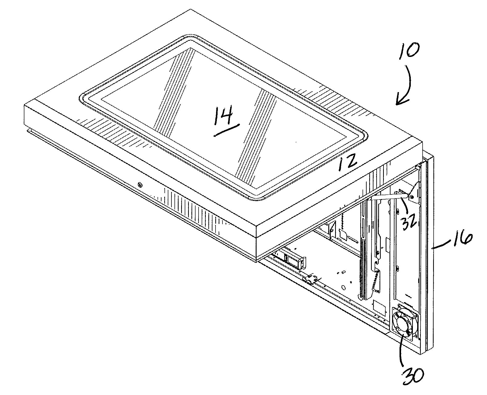
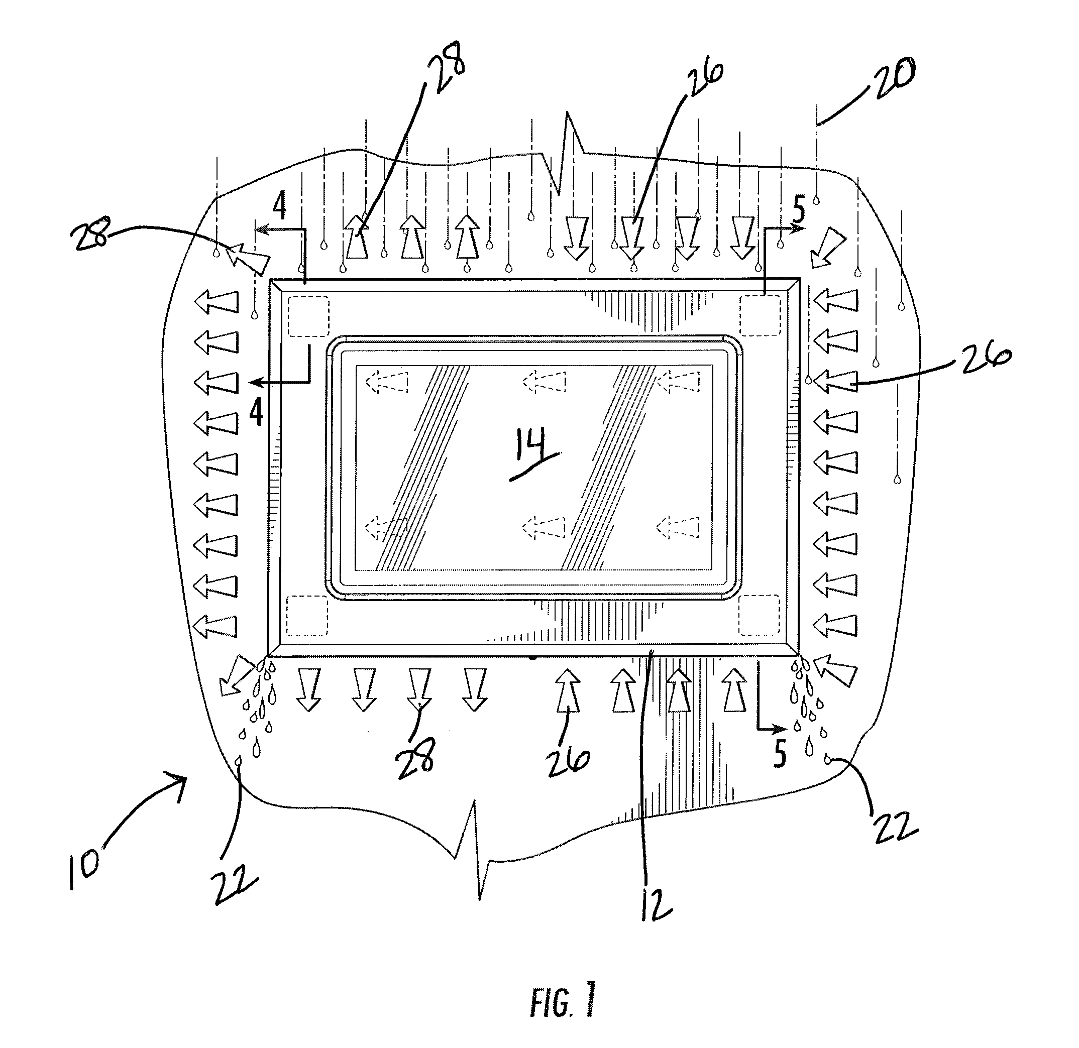
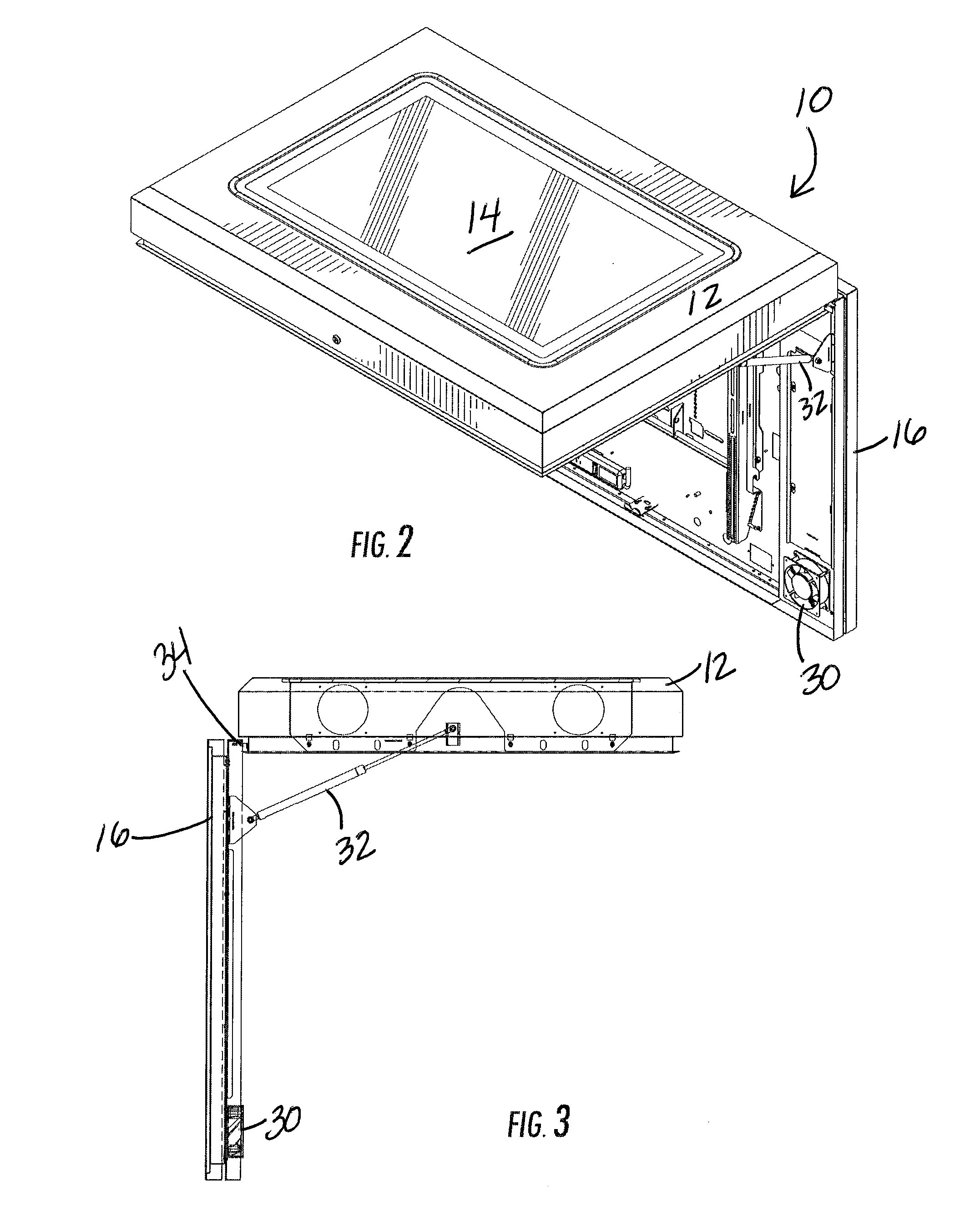
[0027]FIG. 1 is a schematic representation of an enclosure 10 having a cover portion 12 and shown with a preferable transparent window 14. For purposes of convenience, the equipment enclosed is a flat screen video monitor which is a typical but not exclusive application for this device. In such case the window represents the viewing port thru which the screen can be seen. For such equipment, protection against liquids, such as rain, and temperature control of the equipment is essential. The term “waterproof” is intended to mean protection against liquid incursion but not necessarily capable of submersion into water.

[0028]Rain or other forms of liquid are represented by drops 20 at the top edge of the enclosure with drainage liquid shown at the bottom as drops 22. It should be appreciated, that, while the enclosure is shown in the landscape (horizontal) orientation, in the preferred embodiment, it may be “letter” (vertical) or askew and still function as desired. This allows a single...


PUM


Abstract

A waterproof ventilated enclosure for housing equipment is disclosed having the ability to channel water thru the enclosure without touching the equipment and further with the ability to provide active or passive ventilation to the equipment. In the preferred case, the equipment is a video monitor which may be mounted in an outdoor environment. The enclosure includes structures which separate liquid from air through the same or related ports, but prevents commingling.

Description

CROSS-REFERENCE TO RELATED APPLICATIONS[0001]Not ApplicableBACKGROUND[0002]1. Field of the Invention[0003]The present disclosure is directed to the field of waterproof ventilated enclosures for equipment in general, and more particularly to enclosures for equipment sensitive to liquid rain and requires ventilation to expel heat generated by the equipment.[0004]Almost all equipment must be protected from rain or other precipitation. Likewise most equipment generates heat or is sensitive to heat and thus its temperature must be controlled by active or passive ventilation. The combination of these two requirements has become important for visual display screens, for example, which must be placed in outdoor environments. Flat screens in particular are important for outdoor signage but only if waterproofing and heat management can be provided.[0005]The problem is not new to flat screens however, CRTs have similar problems and there has been a long felt need to find a relatively inexpensi...

Claims


Application Information

Patent Timeline
IPC IPC(8): H05K7/20A47B81/00H05K7/18H05K5/02
CPCH05K7/20972
Inventor BOUISSIERE, MICHAEL F.
Owner PREMIER MOUNTS
Learn More