
Ditherless optical modulator control

Active Publication Date: 2009-09-17
LUMENTUM OPERATIONS LLC
View PDF9 Cites 42 Cited by
  • Summary
  • Abstract
  • Description
  • Claims
  • Application Information

AI Technical Summary

Benefits of technology

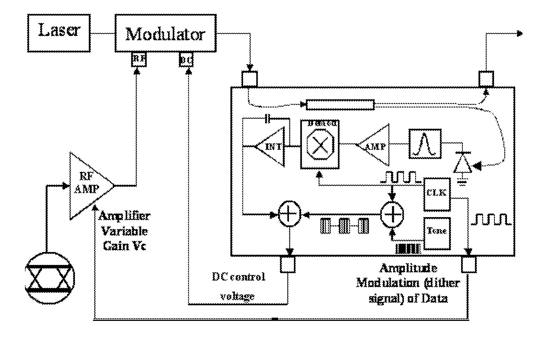
[0011]In accordance with one aspect of the instant invention there is provided system for providing a modulated optical signal comprising: an optical modulator having an input optical port for receiving a light signal, an input electrical port for receiving a data modulation electrical signal for modulating the light signal, and an output port for transmitting a modulated light signal; a reference modulation signal source for generating the data modulation electrical signal and a reference data modulation signal; a tap for separating a portion of the modulated light signal; a monitoring photodiode detector for monitoring the portion of the modulated light signal exiting the optical modulator, and for generating a modulated electrical output tap signal; a signal processor for receiving the reference data modulation signal and the modulated electrical output tap signal, for forming a cross-correlation of the reference data modulation signal and the modulated electrical output tap signal, and for creating a quality of modulation performance signal; and a signal adjuster for adjusting the data modulation electrical signal based on the quality of modulation performance signal in order to improve the modulated optical output signal.

Problems solved by technology

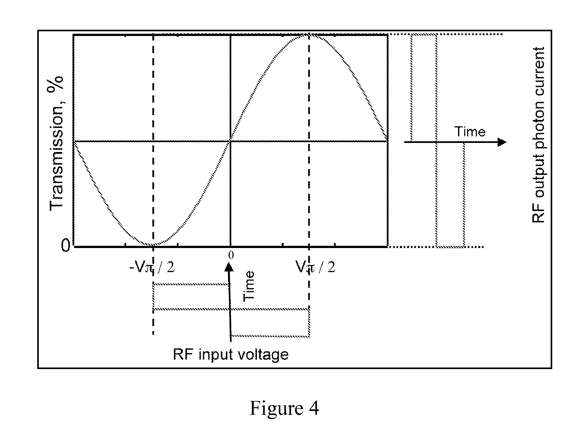
Unfortunately, due to the nature of the electro-optic substrate and the interferometic principles upon which the MZ optical modulator is based, the bias point of these devices tends to drift with changes in wavelength and / or temperature, and / or as a result of aging.
While dither signals typically interfere only minimally with the normal operation of optical modulators, they can unfortunately cause interference in the modulator output.

Method used


Image

  • Ditherless optical modulator control
  • Ditherless optical modulator control
  • Ditherless optical modulator control

Examples


Embodiment Construction

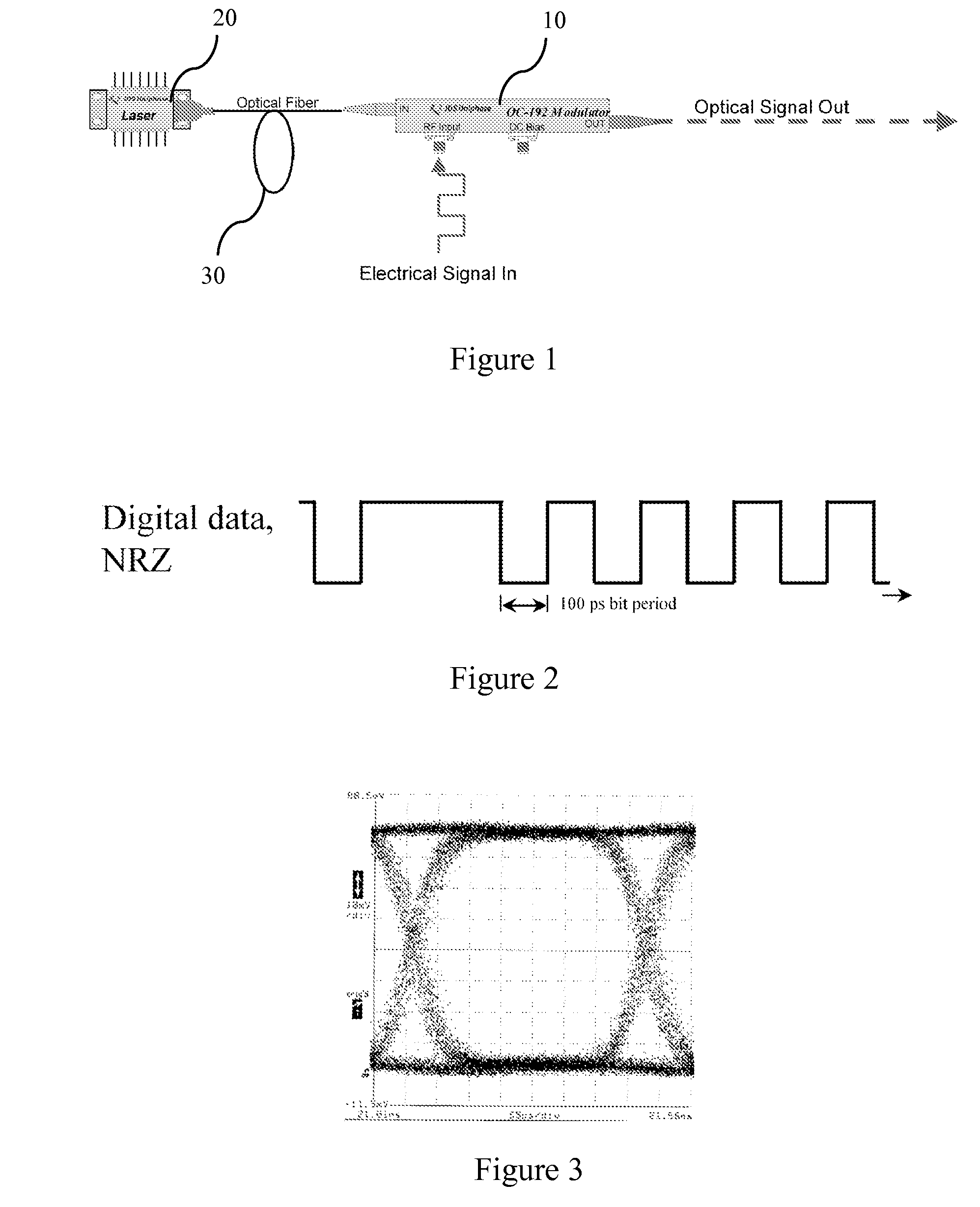
[0040]Referring to FIG. 1, there is shown an external optical modulator 10 for impressing data onto light emitted from a CW laser 20 and transmitted through an optical fiber 30. The optical signal output from this digital optical modulator 10 is regarded as having non-return-to-zero (NRZ) format, because the waveform representing the digital data stays up or down, with no transitions, unless the data value changes from 0 to 1. As illustrated in FIG. 2, which shows the encoded stream for 10 Gb / s data, one characteristic of NRZ data is that the average value of the signal, for an equal density of 1's and 0's is 50% of the waveform height. An average value of 50% can be important for systems that are not DC coupled, as the waveform can be AC coupled, and the top and bottom of the signal should not generally be allowed to drift up and down with changes in the data pattern.

[0041]One way of pictorially showing NRZ data is with an “eye” diagram, which has the series stream 1's and 0's fold...


PUM


Abstract

A method of controlling the operating parameters of an optical modulator, without using a dither signal, is provided. Past operating parameters are compared to present operating parameters using a quality of modulation signal obtained by cross-correlating the data modulation signal used to drive the optical modulator with the modulated optical signal output from the optical modulator. The quality of modulation signal is used to optimize the operating parameters (e.g., bias point) of the optical modulator, or other operating parameters of the arrangement, such as the modulator drive level, timing alignment, etc.

Description

CROSS-REFERENCE TO RELATED APPLICATIONS[0001]This application claims the benefit of U.S. Provisional Application No. 61 / 035,913, filed Mar. 12, 2008, the contents of which are incorporated by reference herein.TECHNICAL FIELD[0002]The present application relates generally to optical modulators and the control thereof, and in particular, to the ditherless control of optical modulators.BACKGROUND[0003]In high-speed optical communication systems, optical modulators are typically used to modulate light emitted from a continuous wave (CW) laser in order to transmit voice, data, and / or video signals. Digital transmission is a special case of general signal transmission using optical modulators, most notably in that the modulation waveform is a large signal modulation, using the full intensity available from the modulator, from on to off.[0004]Optical modulators that use a Mach-Zehnder (MZ) interferometer formed in an electro-optic substrate such as lithium niobate (LiNbO3), have been used ...

Claims


Application Information

Patent Timeline
IPC IPC(8): H04B10/04G02F1/01G02F1/21
CPCH04B10/50572H04B10/50575H04B10/50597H04B10/50593H04B10/50595H04B10/50577
Inventor FARINA, JOSEPH P.MCBRIEN, GREGORY J.
Owner LUMENTUM OPERATIONS LLC
Learn More