Eureka AIR delivers breakthrough ideas for toughest innovation challenges, trusted by R&D personnel around the world.

Endoscope

Inactive Publication Date: 2009-09-17
FUJIFILM CORP
View PDF13 Cites 0 Cited by
  • Summary
  • Abstract
  • Description
  • Claims
  • Application Information

AI Technical Summary

Benefits of technology

[0022]It is a first object of the present invention to solve the above-mentioned problems in the prior art and to provide an endoscope including a movement regulating member which prevents an end portion of the movement regulating member for suppressing radial movement of the contained parts in the curving portion from getting caught by rings of the curving portion to maintain slidability of the contained parts.
[0023]It is a second object of the present invention to solve the above-mentioned problems in the prior art and to provide an endoscope in which, inside the curving portion of the insertion tube, it is possible to prevent or mitigate damage of the contained parts that would be caused by the pressure on the contained parts from the movement regulating member.

Problems solved by technology

Then, they intrude between the other cables and tubes to disorder the arrangement and cause mutual twisting and entanglement of the contained parts, thereby damaging the covering of the contained parts or making it impossible for the curving portion to be smoothly curved or turned back.
In this case, however, an end portion of the movement regulating member would get caught in a gap generated between the rings during the curving motion, resulting in various problems: for example, the end portion would stick out through the gap between the rings; or the movement regulating member would undergo buckling.
Further, if the end portion of the movement regulating member is extended to the position where the radial movement of the contained parts is maximum (i.e., minimum radius-of-curvature position where the radius of curvature of the curving portion is minimum), when the end portion of the movement regulating member exists within the curving portion, that end portion of the movement regulating member is likely to be held or caught in a gap between the rings forming the curving portion, and hence the rings do not move smoothly due to the obstruction by the end portion of the movement regulating member.
Thus, in the actual curving motion of the curving portion of the insertion tube, there is exerted a force causing the contained parts to move toward the outer periphery, and hence the contained parts are pressurized by the movement regulating member to thereby suffer damage.
Here, even if the movement regulating member is arranged inside the curving portion of the insertion tube, when, as in the case of the conventional technologies disclosed in JP 3181707 B and JP 2001-137178 A, the rigidity of the movement regulating member is higher than that of the contained parts, for example, as in the case of the metal coil, the contained parts are pressed hard by the movement regulating member when the curving portion of the insertion tube is curved, with the result that they suffer damage.
Further, even when the movement regulating member is a bar-like or tubular member having elasticity, as disclosed in JP 3181707 B and JP 2001-137178 A, if its diameter is small and its rigidity is higher than that of the contained parts, the contained parts are pressed hard by the movement regulating member when the curving portion of the insertion tube is curved, with the result that they suffer damage.
When such a hard movement regulating member having a predetermined level of rigidity is thus held in contact with the contained parts formed of soft members, the hard movement regulating member is pressed hard against the soft members to crush the same when the curving portion is curved, and hence the soft members suffer damage such as deformation.
Further, when the movement regulating member is strongly brought into contact with the soft members whose surface is soft, the soft members suffer damage such as a surface flaw of the covering thereof.
Further, the wire guide is formed of a hard material of very high rigidity, and hence, when, as in the case of the endoscopes disclosed in JP 3181707 B and JP 2001-137178 A, the contained parts that are soft members are held in contact with the wire guide, the contained parts, in particular, those formed of soft members are pressed hard by the hard wire guide when the curving portion is curved, with the result that the contained parts suffer damage.

Method used


Image

  • Endoscope
  • Endoscope
  • Endoscope

Examples


first embodiment

[0036]First, an endoscope according to a first embodiment of the present invention is described with reference to FIGS. 1 through 6.

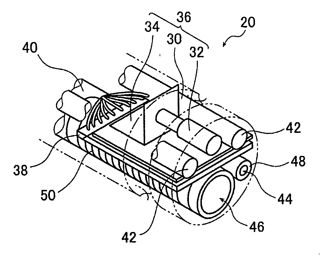
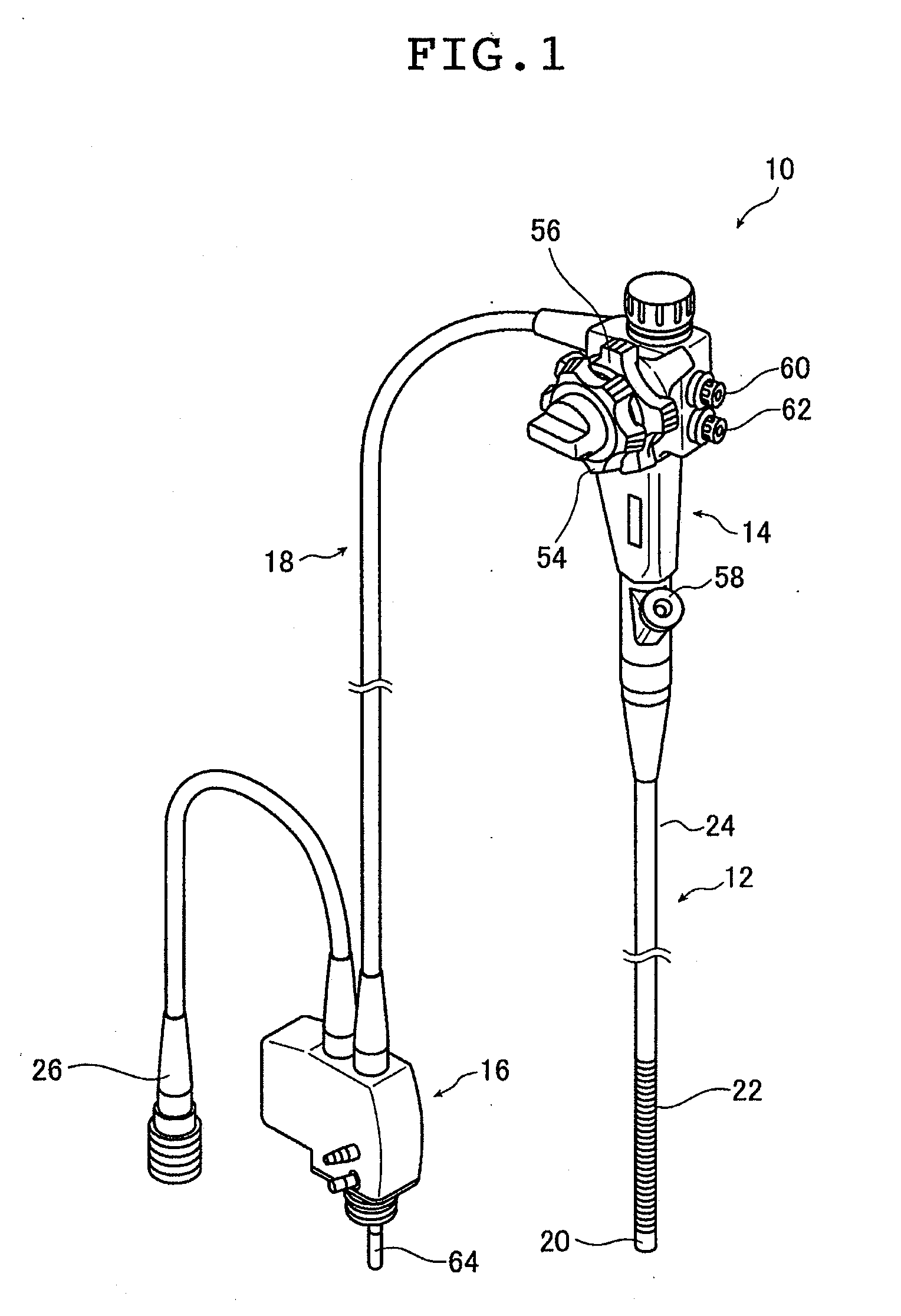
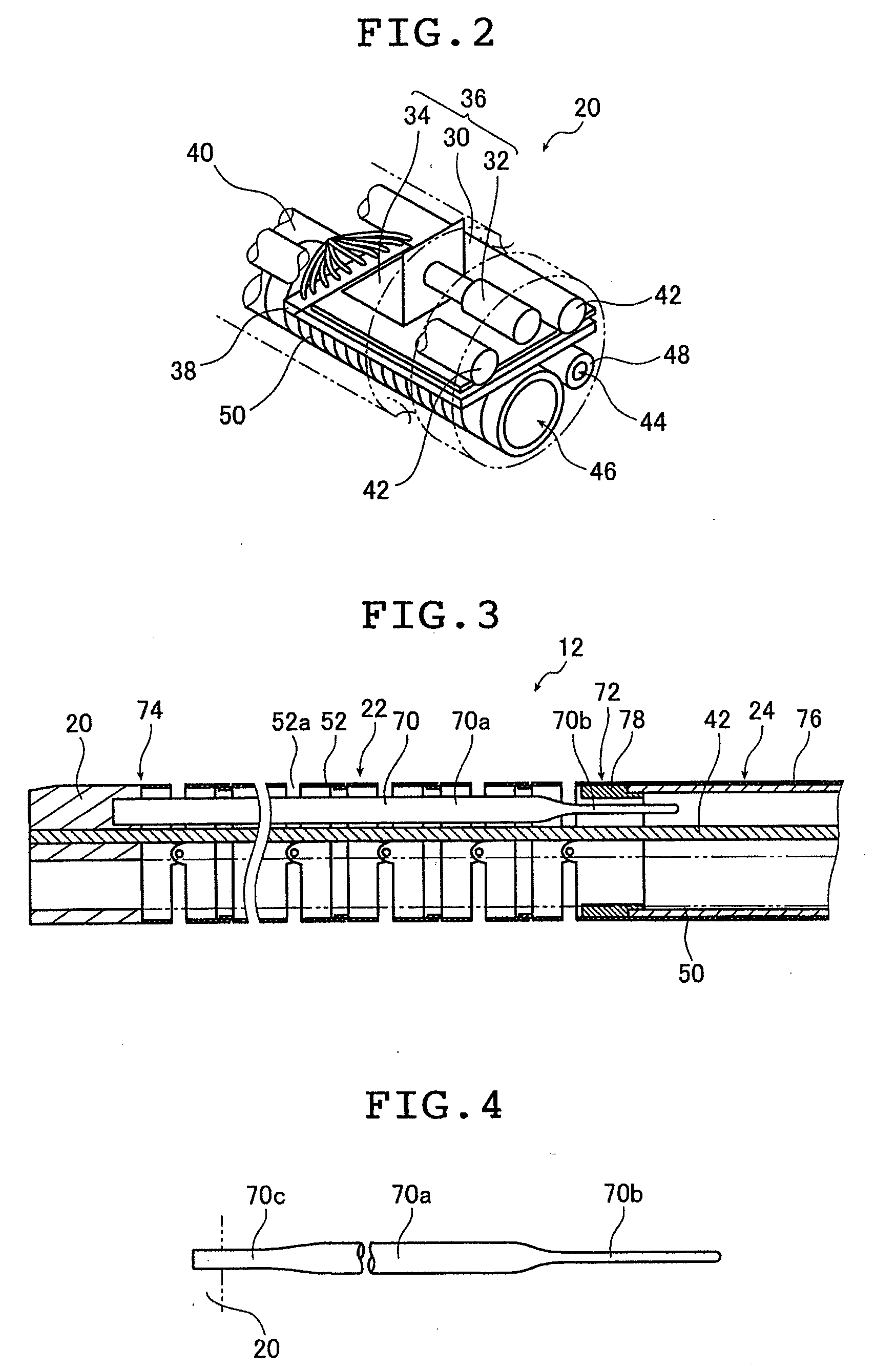
[0037]Here, FIG. 1 is a general perspective view of an endoscope 10 according to the first embodiment of the present invention, FIG. 2 is a perspective view of a hard distal end portion of the endoscope 10, and FIG. 3 is a schematic sectional view of an insertion tube of the endoscope 10.

[0038]As illustrated in FIG. 1, an endoscope 10 is a so-called electronic scope type endoscope which takes an image of an object of inspection such as an inside of a body cavity by using an image pickup device (described in detail below) such as a CCD sensor to directly observe the object of inspection as displayed on a display apparatus and to take a moving image or a still image of the object of inspection. As in the case of an ordinary endoscope, the endoscope 10 includes an insertion tube 12, an operating portion 14, a connector 16, a universal cord 18, etc, and at ...

second embodiment

[0068]Next, an endoscope according to a second embodiment of the present invention is described.

[0069]FIGS. 1 through 3, which are referred to for the description of the endoscope of the first embodiment of the present invention, can also be referred to for the description of the endoscope of the second embodiment of the present invention, and hence a description of the drawings is omitted here.

[0070]FIG. 7 is a cross-sectional view of a curving portion 22a of an insertion tube in the endoscope of the second embodiment of the present invention.

[0071]Inside the curving portion 22a, arranged is a plurality of contained parts such as the data cable 40, the light guides 42, the air-supply / water-supply channel 48 and the forceps channel 50. And movement regulating members 70a regulating radial movements of the contained parts are also arranged in the curving portion 22a together with the contained parts. The movement regulating members 70a are formed of resin tubes whose sectional config...


PUM


Abstract

An endoscope comprises: an insertion tube to be inserted into a body cavity, the insertion tube including a hard distal end portion, a curving portion continuous with the hard distal end portion, and a flexible portion continuous with the curving portion; a contained part of the insertion tube which is accommodated at least inside the curving portion; and at least one movement regulating member which extends inside the curving portion and adapted to regulate at least radial movement of the contained part, one end portion of the position regulating member passing through a rear connecting portion connecting the curving portion and the flexible portion to extend to the flexible portion side, a section of a portion of the movement regulating member inserted into the flexible portion from the rear connecting portion being smaller than a section of a portion of the movement regulating member within the curving portion.

Description

BACKGROUND OF THE INVENTION[0001]The present invention relates to an endoscope including an insertion tube which is inserted into a body cavity and includes a hard distal end portion, a flexible portion, and a curving portion arranged between the hard distal end portion and the flexible portion.[0002]Generally speaking, an endoscope includes a flexible insertion tube to be inserted into a body cavity, and an operating portion which is used to operate the insertion tube to control an advancing direction thereof and to perform image control. Further, the insertion tube includes a hard distal end portion, a curving portion formed by rotatably connecting rings together and operated by the operating portion so as to be curved, and a flexible portion.[0003]Further, as contained parts of the insertion tube, there are inserted, into the curving portion and the flexible portion of the insertion tube, several cables and tubes such as a cable like a signal line for transferring images and pict...

Claims


Application Information

Patent Timeline
IPC IPC(8): A61B1/018
CPCA61B1/0055
Inventor MATSUNAGA, JUNUEDA, YOSHIHIRO
Owner FUJIFILM CORP
Why Eureka
Eureka Blog
Learn More