Manufacturing method of bearing, bearing unit, rotary apparatus, and manufacturing method of sliding member

Inactive Publication Date: 2011-05-26
GAST JAPAN
View PDF8 Cites 0 Cited by
  • Summary
  • Abstract
  • Description
  • Claims
  • Application Information

AI Technical Summary

Benefits of technology

[0011]The AlSi alloy possesses the microstructure where a Si phase having a size of several μm to several tens μm is distributed in an Al phase in an island pattern. Accordingly, in the manufacturing method of a bearing according to the present invention, when anodizing is applied to the AlSi alloy, the portions of the AlSi alloy where the Al phase is exposed are formed in a raised state due to the formation of the aluminum oxide film, and the aluminum oxide film is not formed on the portions of the AlSi alloy where the Si phase is exposed thus forming a large number of indentations (hereinafter, refereed to as dimples) thereon. That is, on the bearing surface of the bearing, the aluminum oxide film having a large number of dimples is formed. Here, the size of the dimples is approximately equal to the size of the Si phases (several μmm to several tens μm) and hence, the lubricant is hardly dissipated from a gap defined between the bearing surface of the bearing and the shaft due to a capillary phenomenon. As a result, according to the manufacturing method of a bearing of the present invention, it is possible to manufacture a bearing which can maintain the bearing performance over a long period.
[0012]Further, when the bearing and the shaft are respectively made of metals, a phenomenon referred to as “galvanic

Problems solved by technology

That is, also with respect to these sliding members in general, the lubricant is liable to be easily dissipated from the gap defined between the sliding member and the member to be in slidable contact with the sliding member in

Method used


Image

  • Manufacturing method of bearing, bearing unit, rotary apparatus, and manufacturing method of sliding member
  • Manufacturing method of bearing, bearing unit, rotary apparatus, and manufacturing method of sliding member
  • Manufacturing method of bearing, bearing unit, rotary apparatus, and manufacturing method of sliding member

Examples


embodiment 1

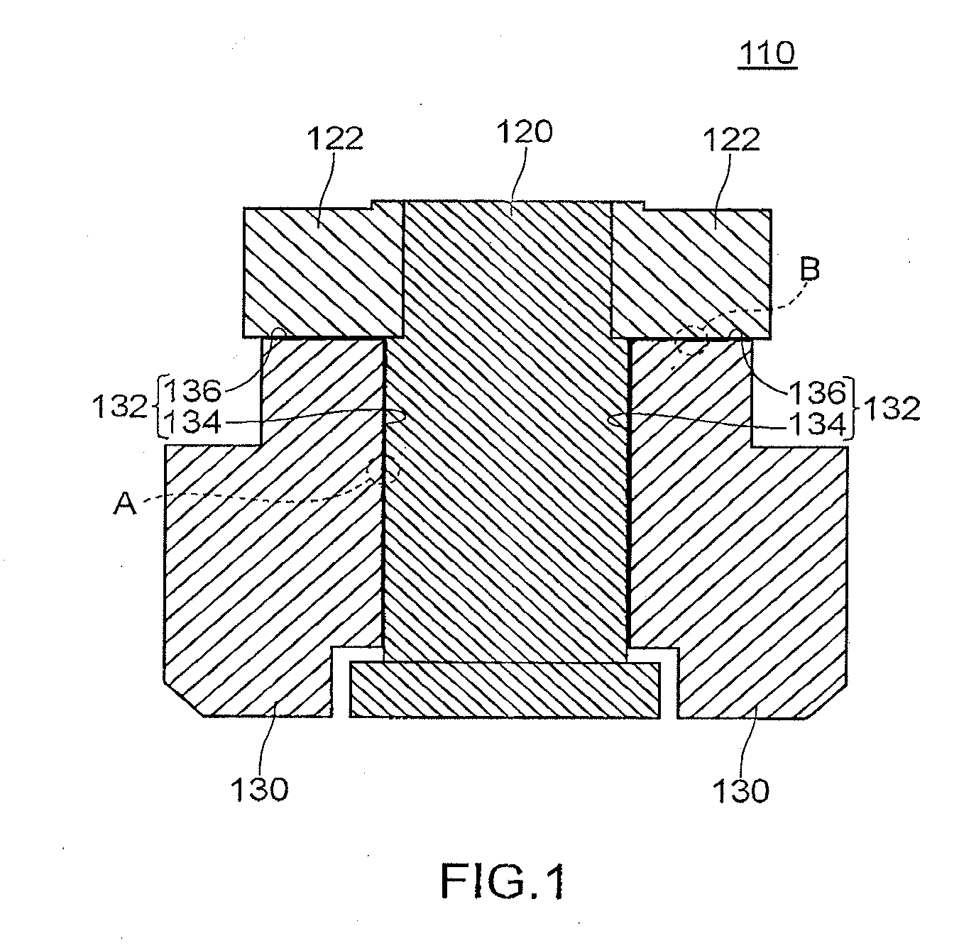
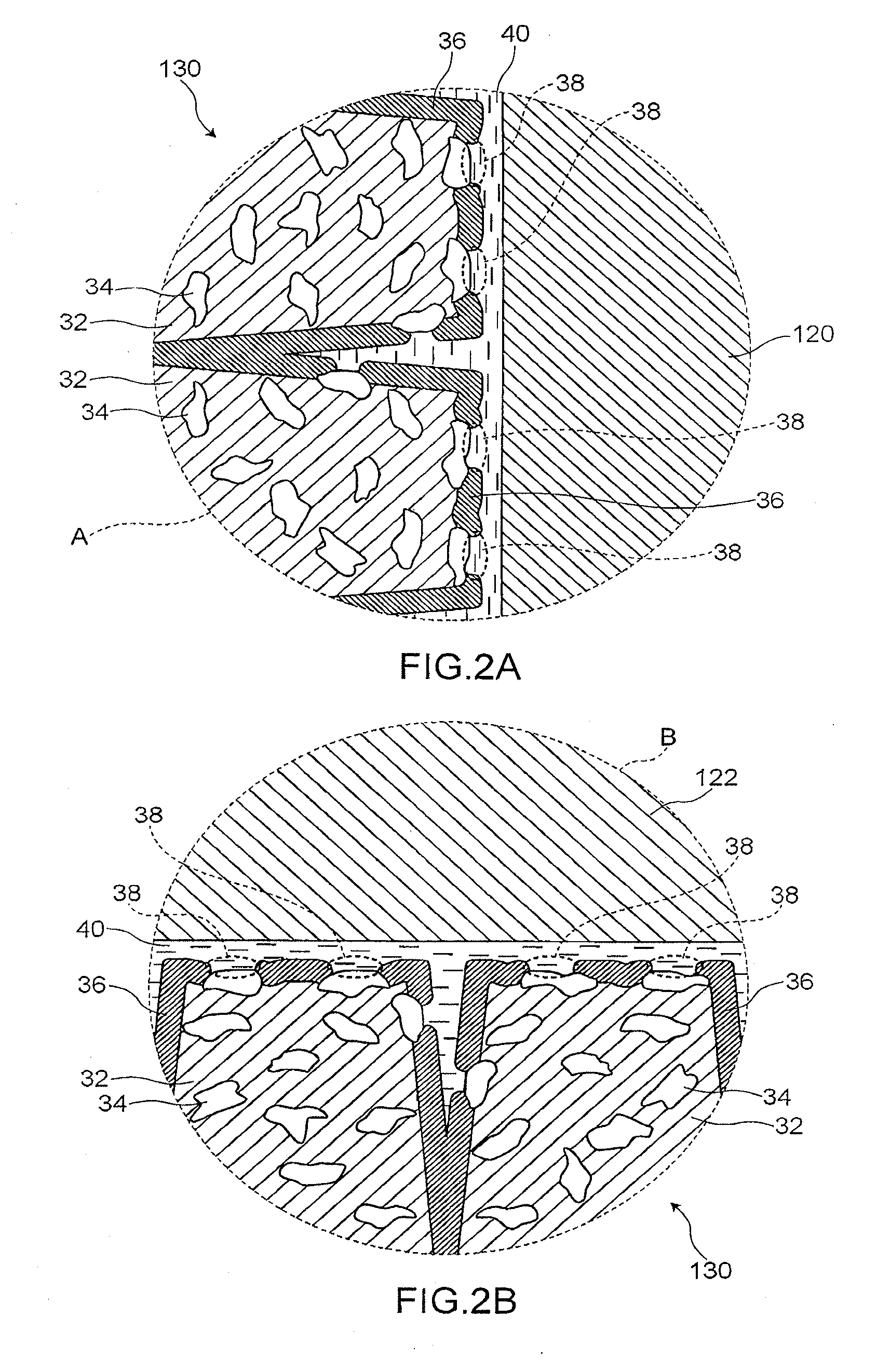
[0068]FIG. 1 is a cross-sectional view for explaining a bearing unit 110 according to an embodiment 1. FIG. 2 is an enlarged cross-sectional view for explaining a surface state of a bearing surface 132. FIG. 2(a) is an enlarged cross-sectional view of an area A in FIG. 1, and FIG. 2(b) is an enlarged cross-sectional view of an area B in FIG. 1. Here, in FIG. 1, an upper side of a surface of the paper corresponds to an upper side of the bearing unit 110 and a lower side of a surface of the paper corresponds to a lower side of the bearing unit 110.

[0069]The bearing unit 110 according to the embodiment 1 includes, as shown in FIG. 1, a bearing (or a bearing sleeve) 130 and a shaft 120 rotatably supported on a bearing surface 132 of the bearing 130.

[0070]The bearing 130 is made of AlSi alloy. The bearing 130 includes a radial bearing surface 134 and a thrust bearing surface 136 as the bearing surface 132.

[0071]The shaft 120 is made of stainless steel. The shaft 120 includes a thrust pla...

embodiment 2

[0106]FIG. 10 is a flowchart for explaining a manufacturing method of a bearing according to an embodiment 2. FIG. 11 is a view for explaining a lubrication film forming step S240. FIG. 11(a1) is a cross-sectional view of a bearing forming member W before performing the lubrication film forming step S240, FIG. 11(a2) is an enlarged cross-sectional view of an area A in FIG. 11(al), FIG. 11(b1) is a cross-sectional view of the bearing forming member W after performing the lubrication film forming step S240, and FIG. 11(b2) is an enlarged cross-sectional view of an area A in FIG. 11(b1). Here, in FIG. 11, parts identical with the parts explained in the embodiment 1 are given same numerals and their detailed explanation is omitted.

[0107]The manufacturing method of the bearing according to the embodiment 2 basically includes steps substantially equal to the steps of the manufacturing method of a bearing according to the embodiment 1. However, the manufacturing method of a bearing accordi...

embodiment 3

[0112]An embodiment 3 is an embodiment explained with respect to a case where the bearing unit of the present invention is applied to a pivot bearing of a hard disc device.

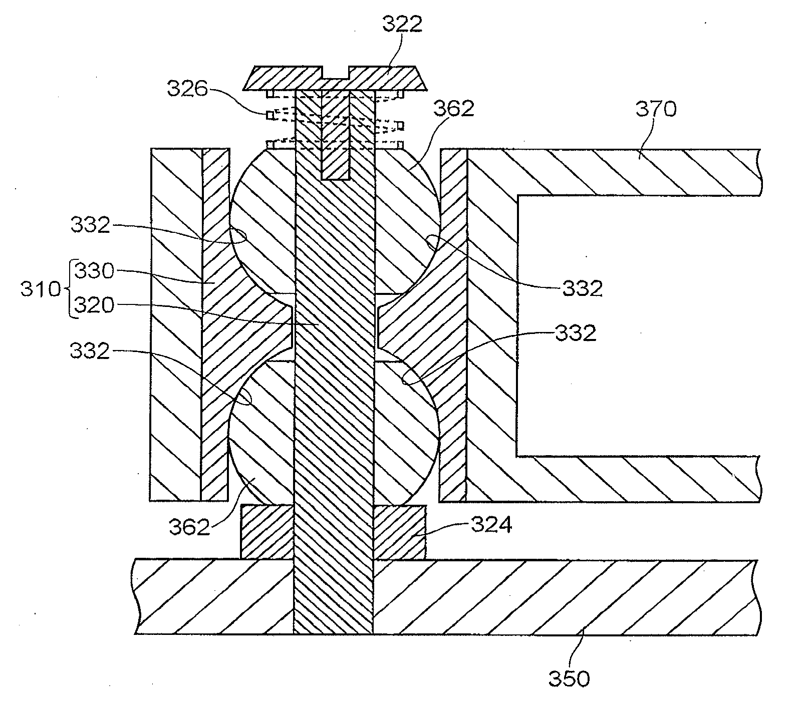
[0113]FIG. 12 is a cross-sectional view for explaining a bearing unit 310 according to the embodiment 3. Here, in FIG. 12, an upper side of a surface of the paper corresponds to an upper side of the bearing unit 310 and a lower side of a surface of the paper corresponds to a lower side of the bearing unit 310.

[0114]The bearing unit 310 according to the embodiment 3 includes, as shown in FIG. 12, a bearing 330 and a shaft 320 rotatably supported on a bearing surface 332 of the bearing 330 by way of spherical slide bodies 362.

[0115]The bearing 330 includes bearing surfaces 332 having a shape corresponding to a shape of the spherical slide bodies 362 (described later). An aluminum oxide film 36 (not shown in the drawing) having a large number of dimples 38 (not shown in the drawing) is formed on the bearing surfaces ...


PUM

PropertyMeasurementUnit
Percent by massaaaaaaaaaa
Thicknessaaaaaaaaaa

Abstract

A manufacturing method of a bearing according to the present invention includes a bearing forming member preparing step S10 for preparing a bearing forming member W made of AlSi alloy containing 5 weight% to 40 weight % of Si, a pressure sizing step S20 which decreases a maximum crest height Rp of a bearing surface 132 by performing pressure sizing of the bearing surface 132 of the bearing forming member W, and an aluminum oxide film forming step S30 for forming an aluminum oxide film 36 on the bearing surface 132 of the bearing forming member W by anodizing the bearing surface 132 of the bearing forming member W in this order. According to the manufacturing method of a bearing of the present invention, it is possible to manufacture a bearing which can maintain the bearing performance over a long period.

Description

TECHNICAL FIELD[0001]The present invention relates to a manufacturing method of a bearing, a bearing unit, a rotary apparatus and a manufacturing method of a sliding member.BACKGROUND ART[0002]Conventionally, there has been known a bearing unit including a bearing and a shaft rotatably supported on a bearing surface of the bearing (see patent document 1, for example).[0003]FIG. 14 is a view for explaining a conventional bearing unit 910. The conventional bearing unit 910 includes, as shown in FIG. 14, a bearing 930 having a bearing surface 932, a bearing 960 having a bearing surface 962, and a shaft 920 rotatably supported on the bearing surface 932 of the bearing 930 and the bearing surface 962 of the bearing 960.[0004]The bearing 930 includes, as the bearing surface 932, a radial bearing surface 934 and a thrust bearing surface 936. The shaft 920 has a thrust plate 922 disposed at a position sandwiched between the thrust bearing surface 936 of the bearing 930 and the bearing surfa...

Claims


Application Information

Patent Timeline
IPC IPC(8): F16C17/10F16C17/00C25D11/02
CPCF16C17/107F16C33/14Y10T29/49705Y10T29/49668Y10T29/49636F16C2220/20F16C2223/42F16C2220/82F16C2223/04F16C2226/12
Inventor YOKOO, YOSHINARI
Owner GAST JAPAN
Why Eureka
Try Eureka