Final gear transmission mechanism for a motorcycle, and motorcycle incorporating same

a transmission mechanism and motorcycle technology, applied in the direction of mechanical control devices, instruments, cycle equipments, etc., can solve problems such as noise, achieve the effect of reducing gear noise with respect to the reducing the torque of the drive shaft, and stable transmission of the rotary drive for

Inactive Publication Date: 2009-09-24
HONDA MOTOR CO LTD
View PDF9 Cites 5 Cited by
  • Summary
  • Abstract
  • Description
  • Claims
  • Application Information

AI Technical Summary

Benefits of technology

[0015]According the first aspect of the present invention, the final gear transmission mechanism includes the first end holding portion for holding the first end of the rear axle attached with the ring gear via the first end bearing in the axial direction of the rear axle, and the fastening member for fastening the second end of the rear axle via the second end bearing from the outside of the gear case.
[0016]The first end of the rear axle is held by the first end holding portion, and the inner race is fastened to the rear axle by the fastening member so that the rear axle may not axially move or slide. Therefore, the rear axle can be held by the gear case such that the rear axle does move in an axial direction thereof. As a result, the axial movement of the ring gear provided at the rear axle can be suppressed.
[0017]If the axial movement of the ring gear is suppressed, the meshing state between the ring gear and the pinion gear provided close to the drive gear to be meshed therewith can be stabilized. If the meshing state between the ring gear and the pinion gear is stabilized, drive torque becomes less variable, which allows for stable transmission of the rotary drive force. In addition, gear noise with respect to the transmission of the rotary drive force can be reduced.
[0018]According the second aspect of the present invention, the gear case is provided with the second end holding portion for holding the second end of the rear axle via the second end bearing in the axial direction of the rear axle, and the lateral surface of the outer race of the second end bearing is abutted against the second end holding portion.
[0019]In addition to the first end bearing, the lateral surface of the outer race of the second end bearing is held by the second end holding portion provided on the gear case. Therefore, the fastening rigidity in the axial direction of the rear axle can further be increased.
[0020]According the third aspect of the present invention, the brake disk is attached so as to be gripped by the rear axle and the rear wheel.

Problems solved by technology

This disadvantageously varies the meshing state between the ring gear 4 and the pinion gear 3, which may probably cause e.g. gear noise.

Method used


Image

  • Final gear transmission mechanism for a motorcycle, and motorcycle incorporating same
  • Final gear transmission mechanism for a motorcycle, and motorcycle incorporating same
  • Final gear transmission mechanism for a motorcycle, and motorcycle incorporating same

Examples


Embodiment Construction

[0028]An embodiment of the present invention will now be described, with reference to the drawings. Throughout this description, relative terms like “upper”, “lower”, “above”, “below”, “front”, “back”, and the like are used in reference to a vantage point of an operator of the vehicle, seated on the driver's seat and facing forward. It should be understood that these terms are used for purposes of illustration, and are not intended to limit the invention.

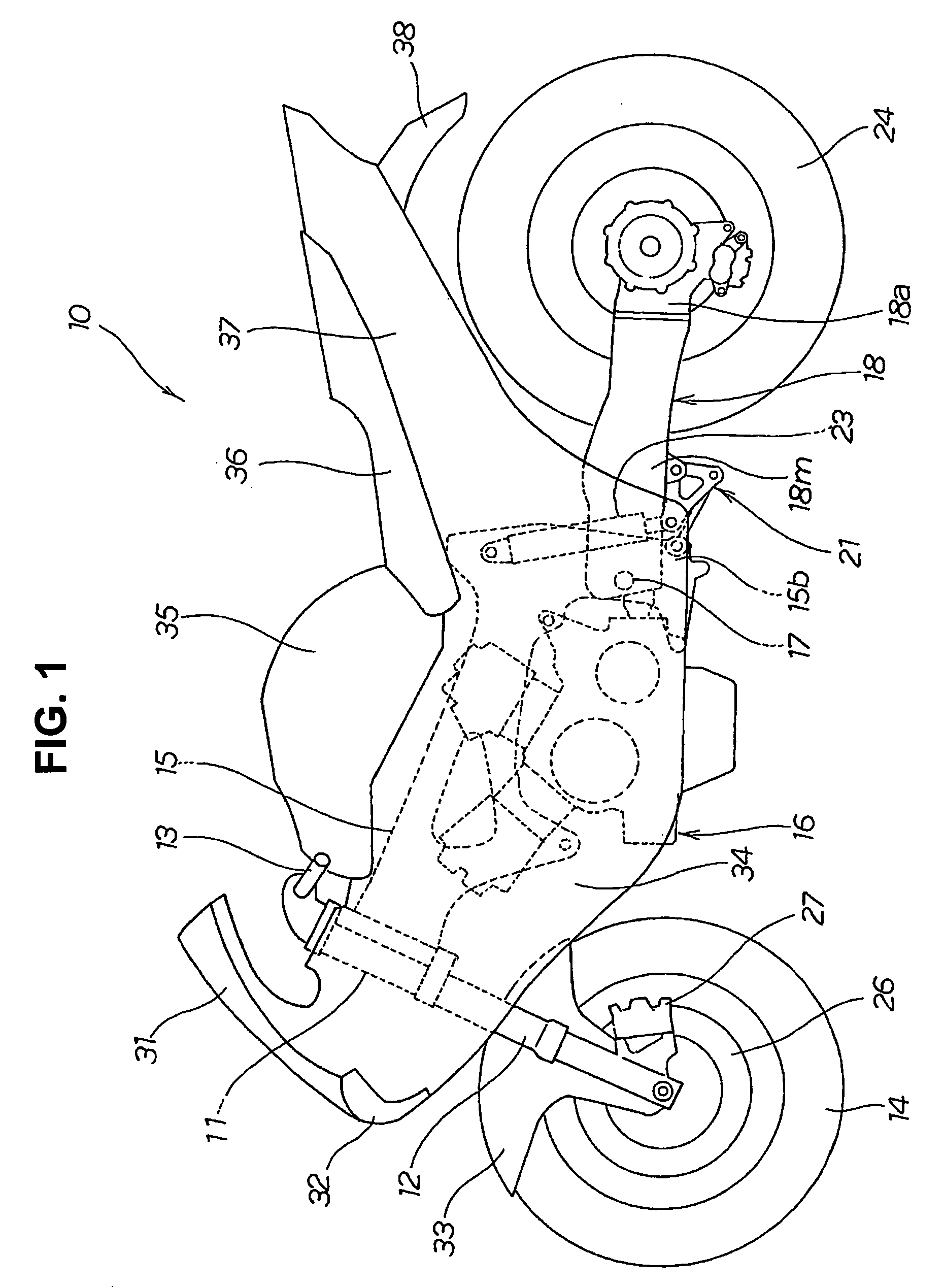
[0029]FIG. 1 is a left side view of a motorcycle 10 according to the present invention. The motorcycle 10, as main components thereof, includes a head pipe 11; a front fork 12 steerably mounted to the head pipe 11; a steering handlebar 13 and a front wheel 14 mounted to an upper end and a lower end of the front fork 12, respectively; a body frame 15 mounted to the head pipe 11 and extended rearwardly.

[0030]The motorcycle 10 further includes an engine 16, as a drive source, suspended by the body frame 15; a swing arm 18 attached to t...


PUM


Abstract

A motorcycle includes a swing arm, a rear wheel mounted on a leading end of the swing arm, a drive shaft disposed in the swing arm, and a final gear transmission mechanism interposed between the drive shaft and the rear wheel. The final gear transmission mechanism includes a gear case mounted on the leading end of the swing arm for supporting a rear axle; a first end bearing and a second end bearing for supporting a first end and a second end of the rear axle, respectively, a ring gear mounted on the rear axle for transmitting the rotary drive force of an engine to the rear axle; a holding portion for holding the first end of the rear axle in the axial direction of the rear axle; and a fastening member for fastening the second end bearing to the second end of the rear axle.

Description

CROSS-REFERENCE TO RELATED APPLICATIONS[0001]The present invention claims priority under 35 USC 119 based on Japanese patent application No. 2008-070236, filed on Mar. 18, 2008. The entire subject matter of this priority document, including specification claims and drawings, is incorporated by reference herein.BACKGROUND OF THE INVENTION[0002]1. Field of the Invention[0003]The present invention relates to a final gear mechanism for a motorcycle. More particularly, the present invention relates a motorcycle in which a final gear transmission mechanism is interposed between a drive shaft and a rear wheel.[0004]2. Description of the Background Art[0005]There is known a motorcycle in which a final gear transmission mechanism for transmitting a rotary drive force of an engine is interposed between a drive shaft and a rear wheel. An example of such final gear transmission mechanism is disclosed in the Japanese Utility Model publication No. 2-393 (see FIG. 5 thereof).[0006]According to the...

Claims


Application Information

Patent Timeline
Patent Type & Authority Applications(United States)
IPC IPC(8): B60K17/00B60T1/06
CPCB62K25/283Y10T74/2191B62M17/00
Inventor NIMURA, TAISUKESAKAI, KIYOTAKAKOFUJI, KENJISHIOMI, YOSHINOBUTOYODA, HIDETOSHIHIGASHI, YASUHIRO
Owner HONDA MOTOR CO LTD
Why Eureka
Try Eureka