Medical or dental handpiece

a technology of handpieces and contraangles, applied in the field of medical or dental contraangle handpieces, can solve the problems of increasing noise, wear, damage, and difficulty in providing an elevated contact ratio of gear systems, and achieve the effect of reducing gear noise, increasing the thickness of each tooth of gears in the first and second gear mechanisms, and improving the engagement of associated tooth surfaces

Active Publication Date: 2016-12-06
MORITA MFG CO LTD
View PDF21 Cites 1 Cited by
  • Summary
  • Abstract
  • Description
  • Claims
  • Application Information

AI Technical Summary

Benefits of technology

[0025]According to the invention, a thickness of each tooth of the gears in the first and second gear mechanisms is increased. Also, the engagements of the associated tooth surfaces are improved, which ensures that a rotational force is well transmitted from the drive gear to the driven gear. Eventually, the invention reduces gear noise, increases a durability of the gear mechanism, and allows a gear design with an improved strength.
[0026]The external diameter of the internal gear can be minimized provided that the external gear engages with the internal gear, which minimizes the external size of the grip and, as a result, ensures the handpiece to be gripped firmly and prevents the grip from being making contacts with the patient, for example, his or her tooth or teeth under treatment.
[0027]The rotation of the treatment tool can be increased significantly by the first and second gear mechanisms and then reduced by the third gear mechanism, which reduces a height of the head while keeping the same tooth thickness for the gears.

Problems solved by technology

According to the handpieces disclosed in JP 2005-520580 A and JP 7-51136 B, the second and third shafts are drivingly connected by the external distal and proximal gears thereof, which makes it difficult to provide an elevated contact ratio for the gear system.
This means that each engaging tooth bears a larger load or bending force, which fails to attain a stable engagement of the gears.
This also increases the noise, wearing, and damages of the tooth.
Also, increasing the diameters of the external gears to increase the contact ratio of the gears results in an unwanted enlargement of the bending portion of the handpiece, accommodating the external gears, which makes it difficult for operators or users of the handpiece to grip it stably or to operate the handpiece as they like.
This in turn may result in that the handpiece touches another tooth or teeth of the patient during cutting treatments.
This increases a backlash between the gears, which increases gear noise and stress acting on the teeth and decreases durability of the teeth.
The transmission mechanism disclosed in JP 2005-42883 A employs the planetary gear mechanism, which complicates its mechanical structure.

Method used


Image

  • Medical or dental handpiece
  • Medical or dental handpiece
  • Medical or dental handpiece

Examples


Embodiment Construction

[0036]The following descriptions of the preferred embodiments are merely exemplary in nature and are in no way intended to limit the invention, its application, or uses.

[0037]Hereinafter, preferred embodiments of the present invention will be described with reference to the accompanying drawings.

[0038]Referring now to the drawings, a medical or dental handpiece according to an embodiment of the present invention will be described below. Although various languages indicating specific directions such as “distal” and “proximal” will be used in the following descriptions for the better understanding of the invention, the technical scope of the invention should not be construed in a limited way by the use of those languages.

[0039]General Construction

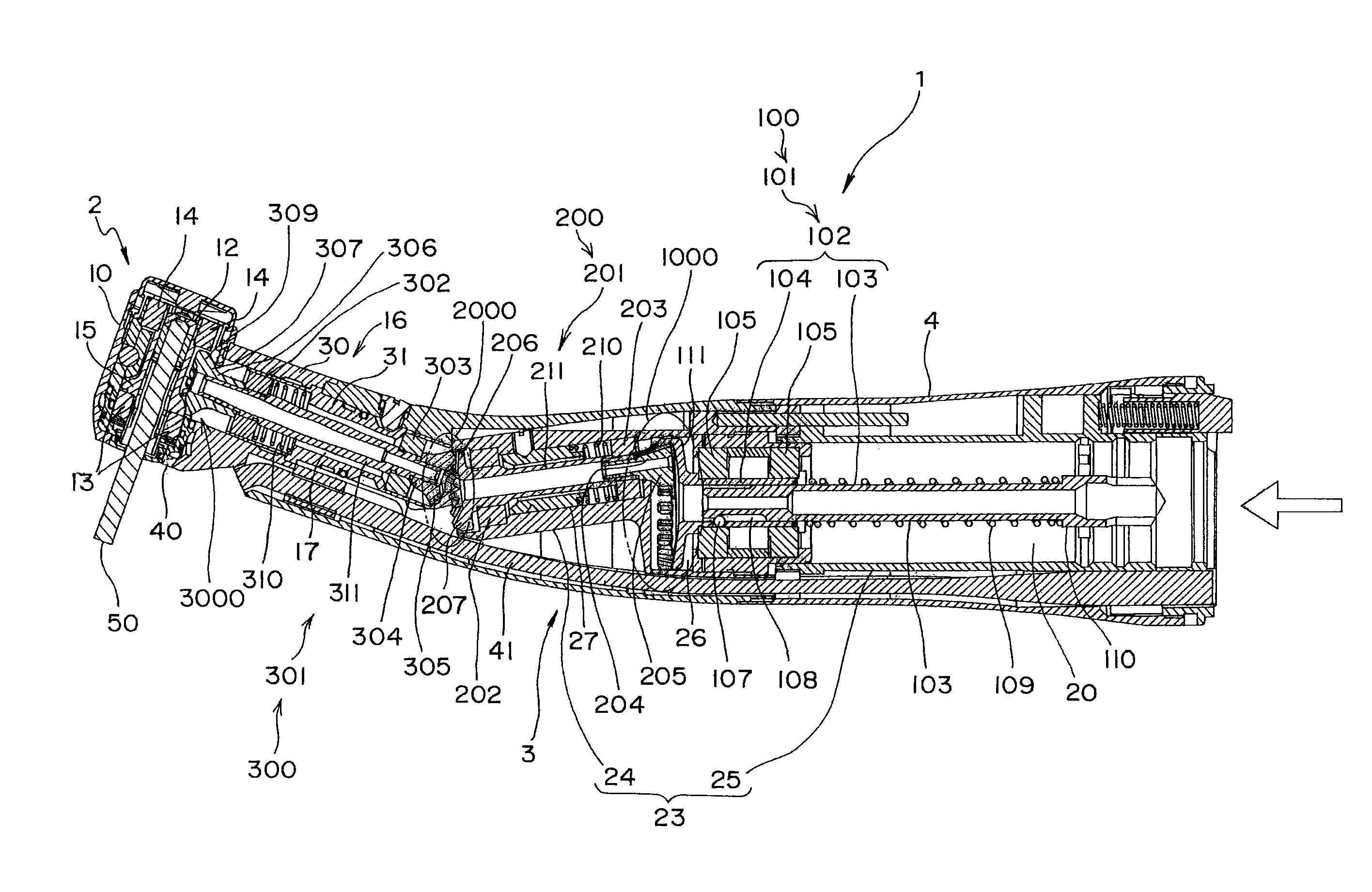
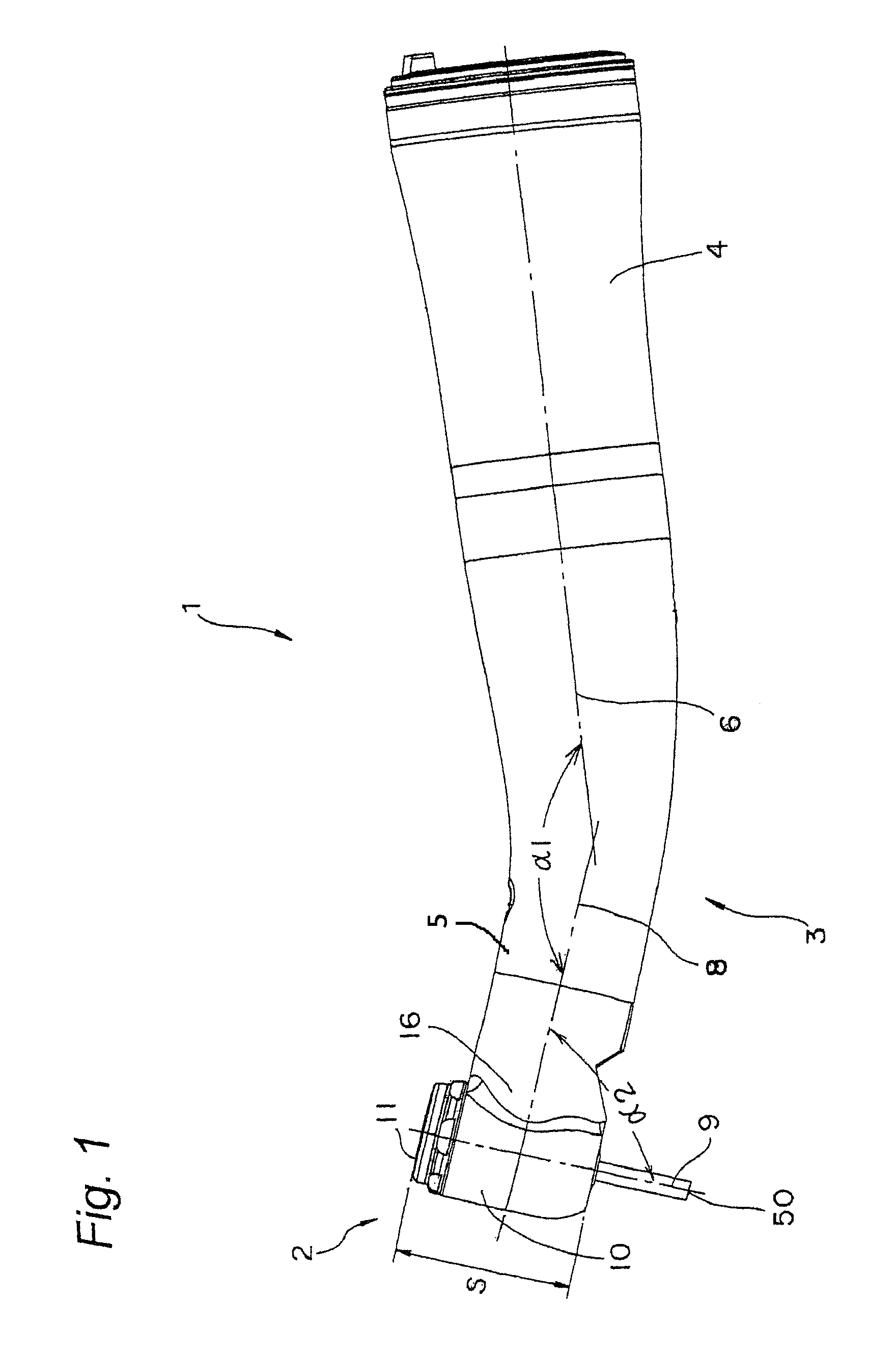
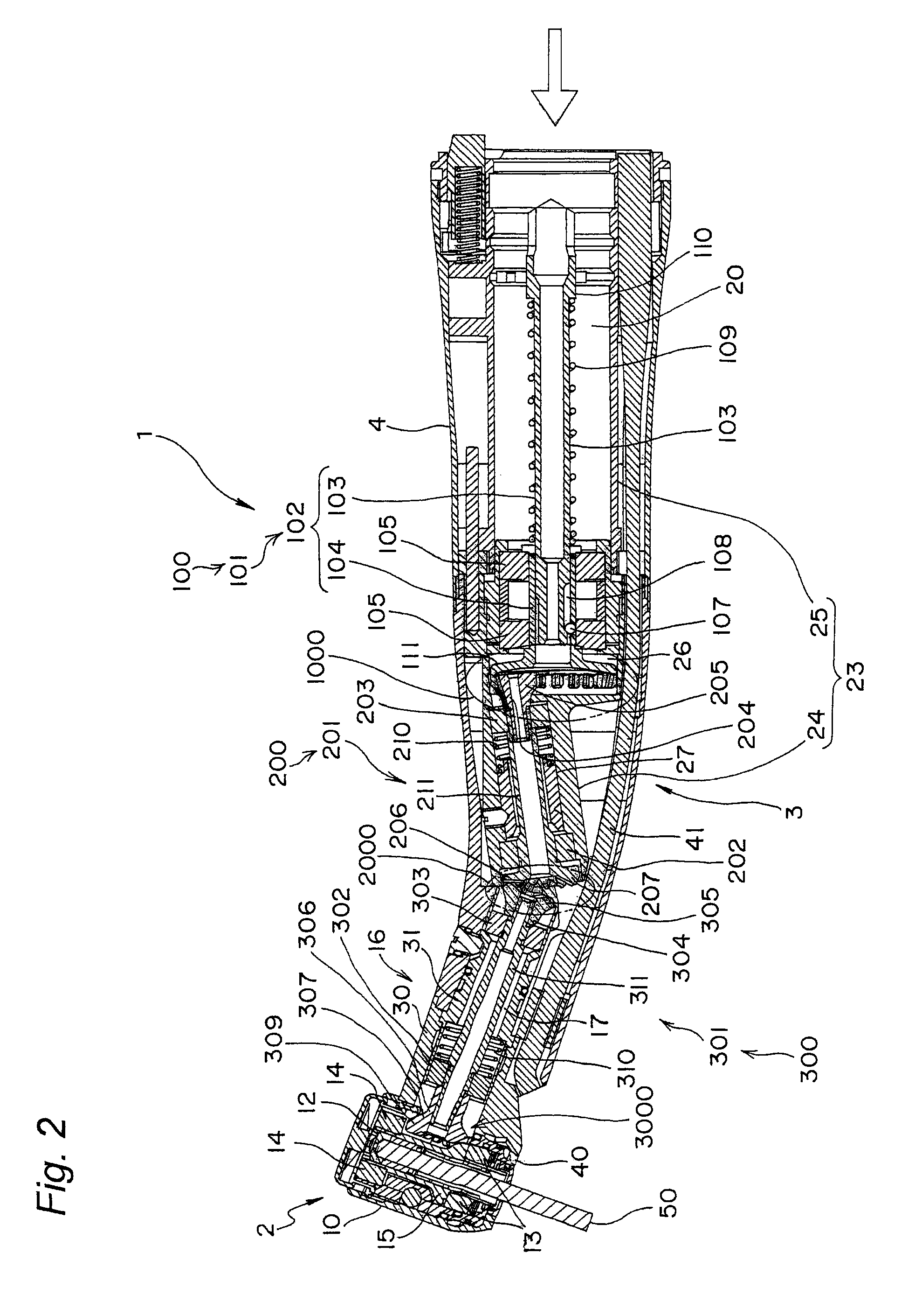
[0040]Referring to FIGS. 1 to 3, the medical or dental handpiece (hereinafter referred to as “handpiece”) according to the embodiment of the invention, generally indicated by reference numeral 1, is a contra-angle handpiece. The handpiece 1 h...


PUM


Abstract

A medical or dental handpiece has a grip 3. The grip 3 includes first to third rotation shafts 101, 201, and 301. The first and second shafts are connected through a first gear mechanism 1000 and the second and third shafts are connected through a second gear mechanism 2000 so that a rotation is transmitted from the first shaft through the first gear mechanism to the second shaft and then from the second shaft through the second gear mechanism to the third shaft. The first or second gear mechanism has an internal gear secured on shaft and an external gear secured on the other shaft, the internal and the external gears being engaged with each other. The external gear is substantially enclosed within a cylindrical plane 1001, 2001 extending along a peripheral edge of the internal gear.

Description

FIELD OF THE INVENTION[0001]The present invention relates to a medical or dental handpiece. In particular, the present invention relates to a medical or dental contra-angle handpiece.BACKGROUND OF THE INVENTION[0002]Conventionally, there has been known a motor-driven, medical or dental contra-angle handpiece. The handpiece has an external cylindrical grip portion and a drive source detachably connected to the proximal end of the grip portion. The distal end of the grip portion has a head in which a treatment or cutting tool is releasably attached. The grip portion is contra-angled so that distal and proximal central axes thereof cross with each other at a certain small angle as shown in JP 2005-520580 A, JP 2009-28512 A, JP 7-51136 B, and JP 2005-42883 A, for example.[0003]The handpieces disclosed in JP 2005-520580 A and JP 7-51136 B are three-stage rotational speed increasing handpiece. According to this handpiece, the rotation from the drive source is transmitted to the first rota...

Claims


Application Information

Patent Timeline
Patent Type & Authority Patents(United States)
IPC IPC(8): A61C1/12A61C1/06A61B17/32
CPCA61C1/12A61C1/06A61B17/32002Y10T74/19679A61B17/00A61C1/185
Inventor TANAKA, HITOSHINAKAYAMA, SHOZO
Owner MORITA MFG CO LTD
Why Eureka
Try Eureka