Control Device for Power Transmission Device and Control Method for Vehicle

a technology of power transmission device and control device, which is applied in the direction of control device, vehicle components, transportation and packaging, etc., can solve the problems of poor response to oil pressure, incomplete switching of gear stage of sub transmission, etc., and achieve the reduction of gear noise or shock generated during switching, the effect of reducing the rotation speed of the output shaft of the automatic transmission

Active Publication Date: 2018-03-29
TOYOTA JIDOSHA KK
View PDF0 Cites 1 Cited by
  • Summary
  • Abstract
  • Description
  • Claims
  • Application Information

AI Technical Summary

Benefits of technology

[0004]In the above-mentioned techniques, switching of the sub transmission is performed via the neutral state. Accordingly, the rotation speed of the output shaft of the automatic transmission is likely to increase. On the other hand, the switching is performed in a state in which the rotation speed of the output shaft of the automatic transmission is decreased by performing the above-mentioned control. As a result, gear noise or shock which is generated during the switching is reduced. However, by engaging or semi-engaging the frictional engagement elements, an engine torque is transmitted to the output shaft of the automatic transmission, a force (a shift load) required for switching the sub transmission from the neutral state to the power transmission state is increased, and thus switching of a gear stage of the sub transmission may be incomplete.
[0005]The disclosure provides a control device and a control method for a vehicle that can decrease a rotation speed of an output shaft of an automatic transmission and reduce a force required for switching a gear stage of a sub transmission at the time of switching the sub transmission in a power transmission device including an automatic transmission and a sub transmission.

Problems solved by technology

However, by engaging or semi-engaging the frictional engagement elements, an engine torque is transmitted to the output shaft of the automatic transmission, a force (a shift load) required for switching the sub transmission from the neutral state to the power transmission state is increased, and thus switching of a gear stage of the sub transmission may be incomplete.
When the oil temperature of the hydraulic oil is in a low temperature range lower than a low temperature threshold value, responsiveness of an oil pressure is poor.

Method used


Image

  • Control Device for Power Transmission Device and Control Method for Vehicle
  • Control Device for Power Transmission Device and Control Method for Vehicle
  • Control Device for Power Transmission Device and Control Method for Vehicle

Examples


Embodiment Construction

[0030]Hereinafter, embodiments of the disclosure will be described in detail with reference to the accompanying drawings. In the following embodiments, the drawings are appropriately simplified or modified and dimensional ratios, shapes, and the like of elements do not match actual ones.

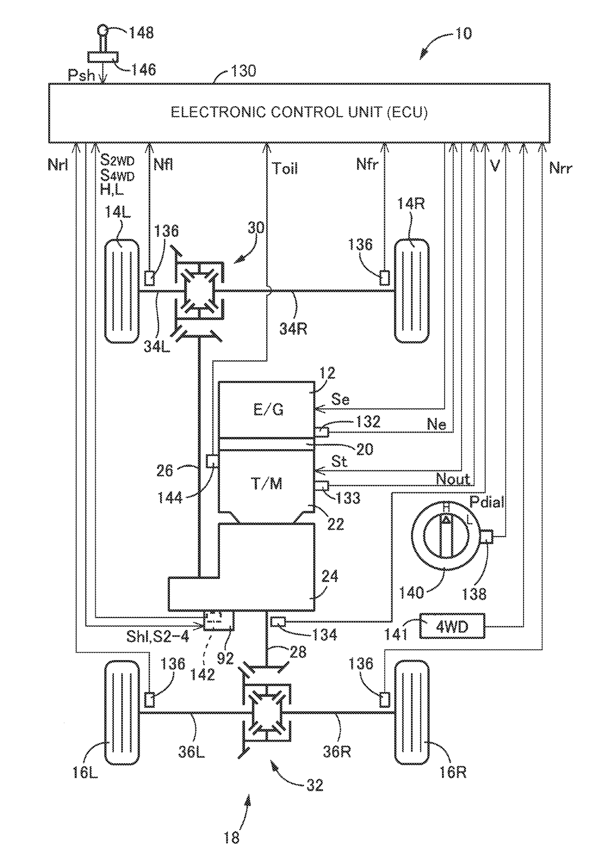
[0031]FIG. 1 is a block diagram illustrating a configuration of a vehicle 10 according to an embodiment of the disclosure, where principal parts of a control system disposed in the vehicle 10 are illustrated. In FIG. 1, the vehicle 10 is, for example, a four-wheel-drive vehicle based on a front-engine rear-driving (FR) system and includes a power transmission device 18 (hereinafter referred to as a power transmission device 18) that transmits power from an engine 12 as a driving force source for traveling to a pair of right and left front wheels 14L, 14R (which are referred to as front wheels 14 when the two are not particularly distinguished) as sub driving wheels and a pair of right and left rear w...


PUM


Abstract

A control device for a power transmission device including an automatic transmission and a sub transmission is provided. The control device includes an electronic control unit. The electronic control unit is configured to perform a rotation speed decrease control in which at least one frictional engagement device is controlled to be an engaged state or a semi-engaged state at a time when switching of gear stage of the sub transmission is started or a time when the switching is started. The electronic control unit is configured to end the rotation speed decrease control during switching of the gear stage. The electronic control unit is configured to switch the sub transmission from the power transmission cutoff state to a state in which one of the high-speed engagement element and the low-speed engagement element is engaged, during disengagement of the at least one frictional engagement device.

Description

INCORPORATION BY REFERENCE[0001]The disclosure of Japanese Patent Application No. 2016-187548 filed on Sep. 26, 2016 including the specification, drawings and abstract is incorporated herein by reference in its entirety.BACKGROUND1. Technical Field[0002]The disclosure relates to a control device for a power transmission device including an automatic transmission and a sub transmission and a control method for a vehicle.2. Description of Related Art[0003]A power transmission device for a vehicle is disclosed in Japanese Patent Application Publication No. 2010-247603 (JP 2010-247603 A) and Japanese Patent Application Publication No. 2010-209949 (JP 2010-209949 A). The power transmission device includes an automatic transmission and a sub transmission. A configuration in which a transfer including a sub transmission is disposed downstream from a main transmission (an automatic transmission) is described in JP 2010-247603 A. In JP 2010-247603 A, when the sub transmission is switched fro...

Claims


Application Information

Patent Timeline
Patent Type & Authority Applications(United States)
IPC IPC(8): B60W10/10B60W20/30B60W30/19B60W10/02B60W10/08B60W10/119
CPCB60W10/10B60W20/30B60W30/19B60W10/02B60W10/08B60W10/119B60K17/08B60K17/344B60K20/00B60K23/08B60K2023/0858B60W10/06B60W10/11B60W20/00B60W2510/107Y02T10/62
Inventor ARAI, MASAYUKITAKAIRA, KOJITAKAHASHI, AKINORI
Owner TOYOTA JIDOSHA KK
Why Eureka
Try Eureka