Pdp driving apparatus and plasma display
a driving apparatus and plasma display technology, applied in electrical devices, light sources, instruments, etc., can solve the problems of reducing the number of parts at the same time, and it is difficult to save power consumption, so as to reduce the size of the driving apparatus, reduce the mounting area, and reduce the wiring impedance
- Summary
- Abstract
- Description
- Claims
- Application Information
AI Technical Summary
Benefits of technology
Problems solved by technology
Method used
Image

Examples
embodiment 1
1.1 Configuration
1.1.1 Plasma Display
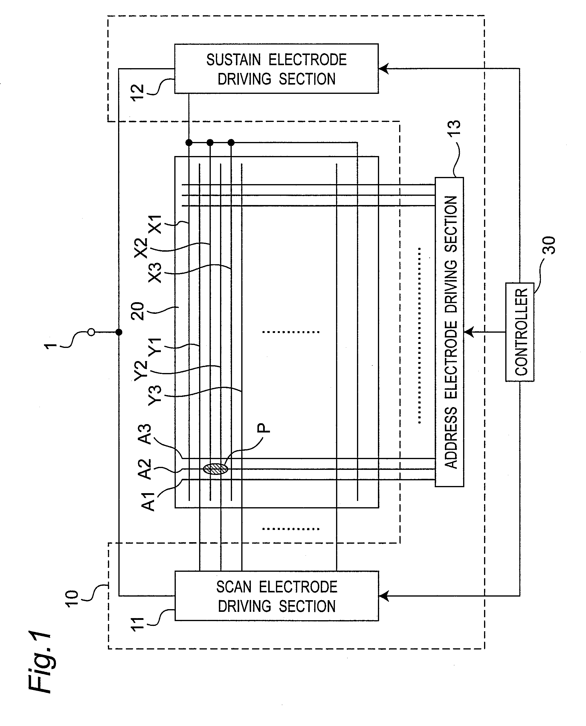
[0071]FIG. 1 is a block diagram showing a configuration of a plasma display in an embodiment of the invention. The plasma display includes a PDP driving apparatus 10, a plasma display panel (PDP) 20, and a controller 30.
(Plasma Display Panel)
[0072]The PDP 20 is, for example, of AC type, having three-electrode surface discharge type structure. On a back surface of the PDP 20, address electrodes A1, A2, A3, . . . are disposed along the width direction of the panel. On a front surface of the PDP 20, sustain electrodes X1, X2, X3, . . . and scan electrodes Y1, Y2, Y3, . . . are disposed alternately along the longitudinal direction of the panel. The sustain electrodes X1, X2, X3, . . . are mutually coupled to be substantially equal in the potential. The address electrodes A1, A2, A3, . . . , and scan electrodes Y1, Y2, Y3, . . . can be controlled individually for the potential.
[0073]A discharge cell is disposed at an intersection (for example, shaded ...
embodiment 2
[0153]The plasma display of this embodiment differs from embodiment 1 only in the structure of scan electrode driving section 11.
2.1 Scan Electrode Driving Section
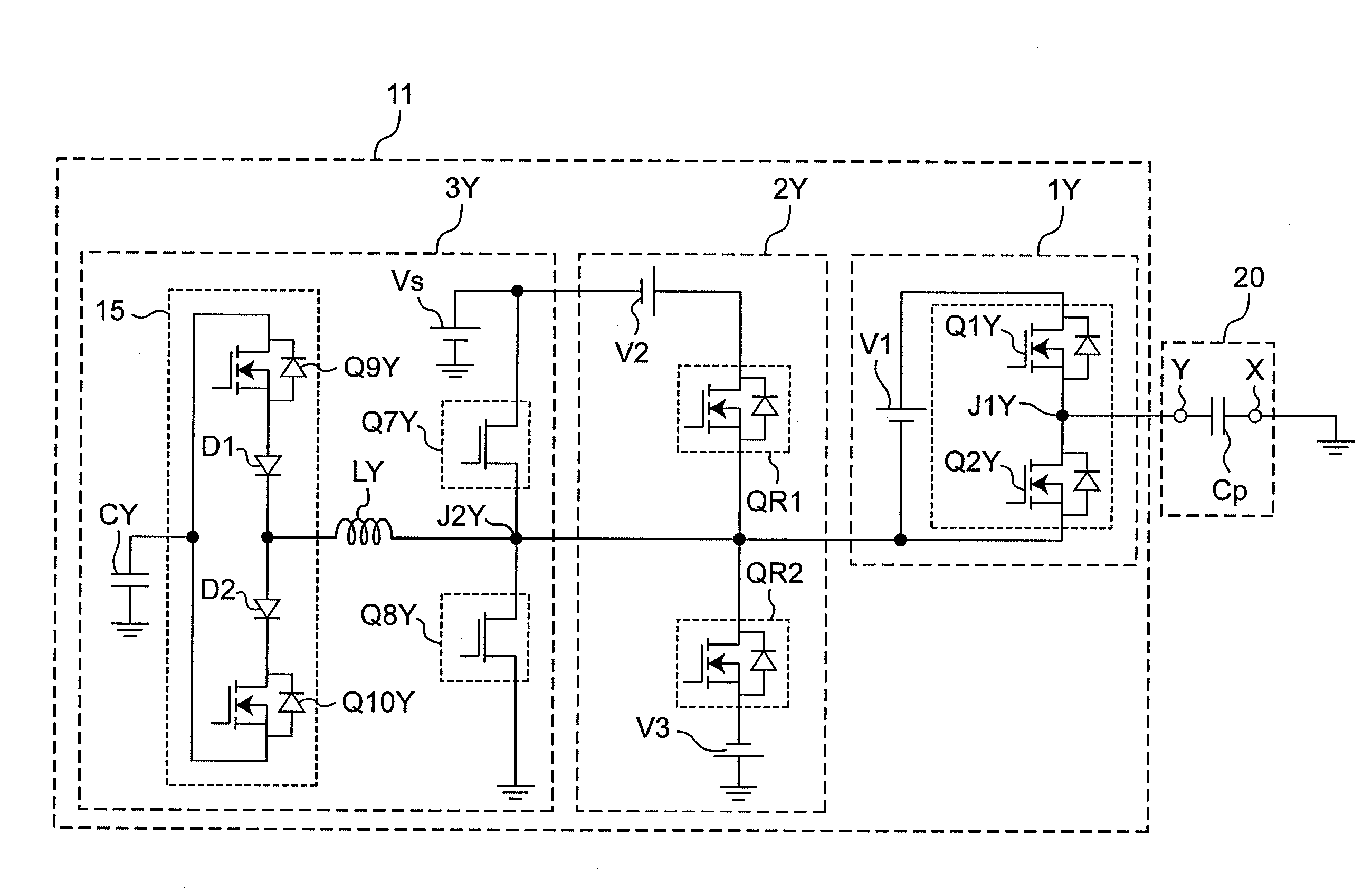
[0154]FIG. 8 shows a detailed configuration of the scan electrode driving section 11 of the present embodiment.
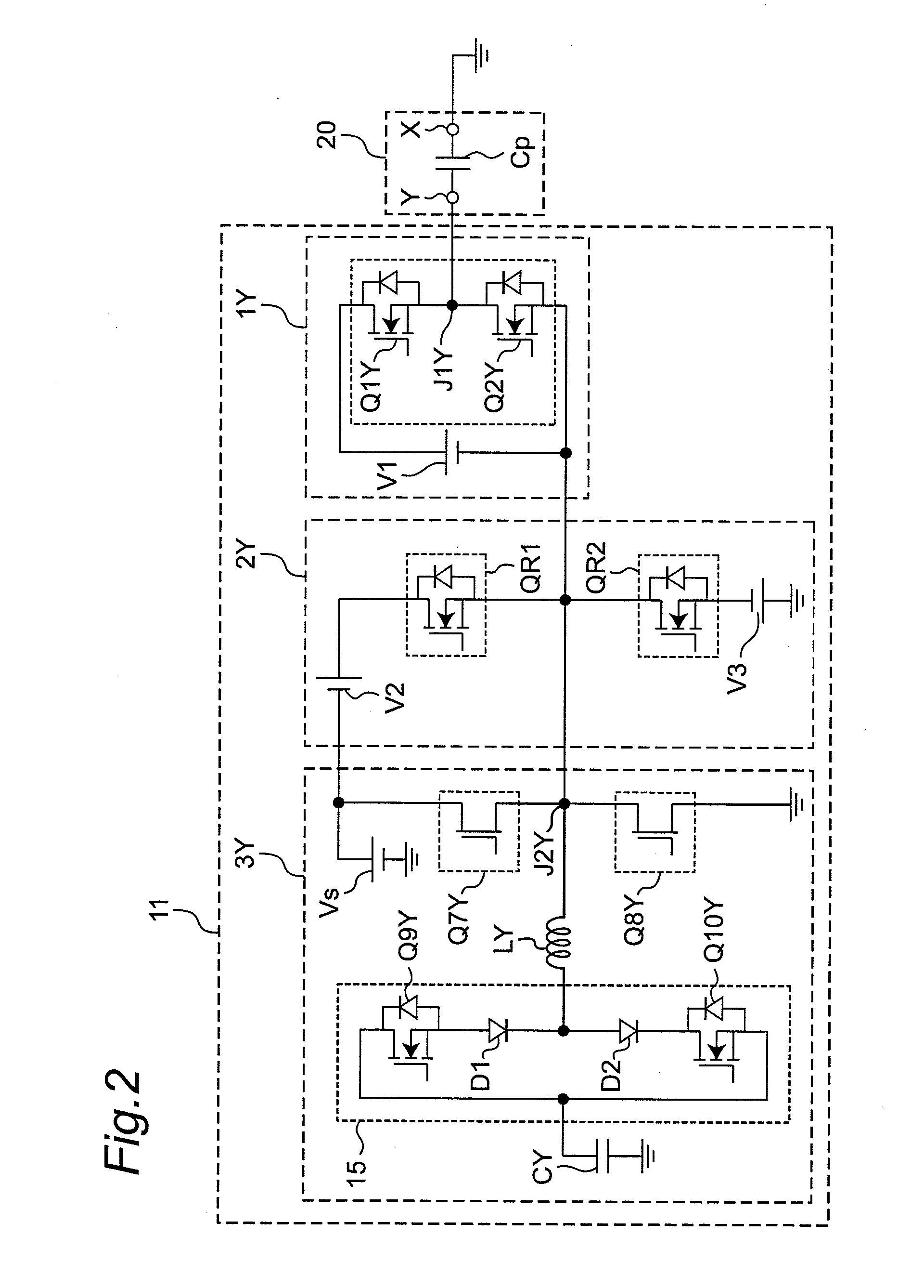
[0155]The scan electrode driving section 11 according to the present embodiment is different from the one of embodiment 1 shown in FIG. 2 in the configuration of the scan pulse generating section 1Y and the reset pulse generating section 2Y. Other components are the same as those in embodiment 1.
(Scan Pulse Generating Section)
[0156]The scan pulse generating section 1Y includes a first constant voltage source V1, a high side scan switch element Q1Y, a low side scan switch element Q2Y, and V1 applying switch elements Q3Y and Q4Y.
[0157]The positive electrode of the first constant voltage source V1 is connected to the drain of the V1 applying switch element Q3Y. The source of the V1 applying switch element Q3Y is conn...
embodiment 3
[0176]FIG. 10 shows a circuit configuration of a scan electrode driving section according to the present embodiment. A plasma display according to the present embodiment is different from the one of embodiment 1 shown in FIG. 2 in the configuration of the high side ramp waveform generating section in the scan electrode driving section 11. There is also a difference in that a fourth constant voltage source V4 is provided instead of the second constant voltage source V2.
3.1. High Side Ramp Waveform Generating Section
[0177]FIG. 11 shows a detailed configuration of a high side ramp waveform generating section QR1a in the scan electrode driving section 11 according to the present embodiment. The high side ramp waveform generating section QR1a shown in the figure includes a high side NMOS (41), a ramp capacitor C1, a ramp Zener diode ZD1, and a gate circuit 33.
[0178]The high side NMOS (41) has its drain connected to the positive electrode of the fourth constant voltage source V4 and its s...
PUM
 Abstract
Description
Claims
Application Information
 - R&D
- Intellectual Property
- Life Sciences
- Materials
- Tech Scout
- Unparalleled Data Quality
- Higher Quality Content
- 60% Fewer Hallucinations
Browse by: Latest US Patents, China's latest patents, Technical Efficacy Thesaurus, Application Domain, Technology Topic, Popular Technical Reports.
© 2025 PatSnap. All rights reserved.Legal|Privacy policy|Modern Slavery Act Transparency Statement|Sitemap|About US| Contact US: help@patsnap.com