Ferroelectric lens

a ferroelectric lens and lens body technology, applied in the field of lenses, can solve the problems of increasing the cost of the device, difficult to fabricate the large-scale (>55 cmsup>2/sup>) plate of the design with acceptable densification and uniformity, and achieves less complex manufacturing, less expensive, and less driving voltage

Active Publication Date: 2009-09-24
TELEFON AB LM ERICSSON (PUBL)
View PDF5 Cites 0 Cited by
  • Summary
  • Abstract
  • Description
  • Claims
  • Application Information

AI Technical Summary

Benefits of technology

[0006]There is thus a need for a ferroelectric lens for steering the output direction of an incident electromagnetic beam which is less expensive and less complex to manufacture than those known at present. In addition, such a new lens should also need lower driving voltages than lenses which are known at present.
[0009]According to the invention, the lens's main body of ferroelectric material comprises a plurality of discrete slabs of the ferroelectric material, each slab in said plurality also comprising a first and a second electrode of an electrically conducting material. Also, the means for creating a DC-field can create a gradient DC-field in said first direction, using the first and second electrodes in the plurality of slabs, by means of which the dielectric constant in the main body will also be a gradient in said first direction, thus enabling steering of the exiting electromagnetic wave, and offer design flexibility with low expenses.
[0010]Thus, by means of the invention, a beam-steering lens made from a ferroelectric material is obtained which will be less expensive to produce than previously known such lenses, and, as will become apparent from the more detailed description, will also require much lower control voltages than previously known such lenses.

Problems solved by technology

A drawback of the device discussed in this article is the complexity of the design and the price.
The device uses a multitude of traditional waveguides filled with ferroelectric materials and input / output matching sections which would increase the cost of the device.
Additionally, the fabrication of a large area ferroelectric plates (lens) as disclosed in this paper is complicated—it is hard to fabricate the large size (>5×5 cm2) plates of the design with acceptable densification and uniformity.

Method used


Image

  • Ferroelectric lens
  • Ferroelectric lens
  • Ferroelectric lens

Examples


embodiment 500

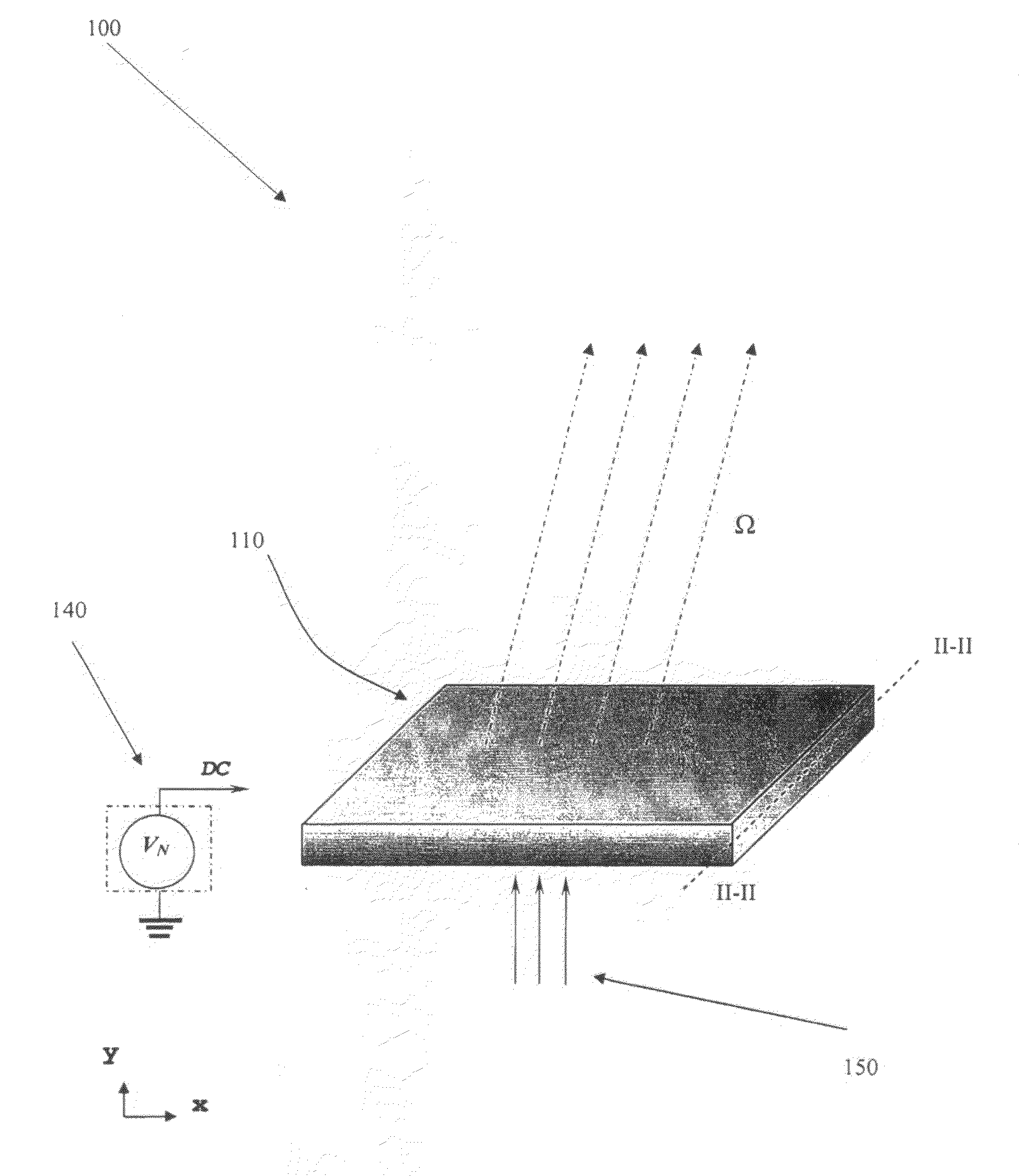
[0060]FIG. 5 shows a different embodiment 500 of the invention, by means of which the direction of the exiting electromagnetic beam can be controlled in both the x- and the y-direction, with renewed reference to the coordinate system shown in FIG. 3 and also in FIG. 5.

[0061]As with the previous embodiments, the embodiment 500 is based on a body of ferroelectric material 510. The lens 500 comprises one or several matching transformers at the main surfaces of the body, which is in similarity to the embodiment shown and explained in conjunction with FIGS. 2-4, for which reason the transformers will not be described again here.

[0062]The ferroelectric body 510 is also comprised of a plurality of slabs, 51011-510NN, which in the drawing are shown as rectangular box-like structures arranged as a matrix with N rows and N columns. One of the slabs used in the embodiment 500 is shown in more detail in FIG. 6.

[0063]As with the slabs of the previous embodiment, the slab 510XX shown in FIG. 6 co...

embodiment 700

[0076]One example of an alternative embodiment 700 is shown in FIG. 7: the ferroelectric lens 700 comprises a ferroelectric body 710, with a matching transformer 720, 722, adjacent to each of two main surfaces 707, 708, of the ferroelectric body 710.

[0077]However, as an alternative, the lens 700 has a concave first main surface 707 and a plane second main surface 708, with the respective matching transformers 720, 722, having corresponding shapes. This shape of the components of the lens make it possible to, for example, shape the beam form and / or beam width of the output beam.

[0078]Some examples of materials and dimensions for a lens according to the invention will also be given. It should be pointed out that although these materials and examples are suitable for a lens according to the invention, these are examples only, and should not be seen as restricting the scope of the invention.

[0079]As an example of a suitable material for the ferroelectric slabs of the ferroelectric body,...


PUM


Abstract

A lens (300, 500) is disclosed for steering the exit direction (Ω) of an incident electromagnetic wave. The lens comprises a main body (210, 510) of a ferroelectric material with a first main surface (207, 507) and a first transformer (220, 222). The electromagnetic wave enters and exits the lens through the transformer, and the lens comprises means (370, 380) for creating a DC-field in a first direction in the main body. The main body (210, 510) of ferroelectric material comprises a plurality (21011-210NN, 51011-510NN) of slabs of the ferroelectric material, each slab also comprising a first (403, 603) and a second electrode of a conducting material. The means for creating a DC-field can create a gradient DC-field in the first direction using the first and second electrodes, so that the dielectric constant in the main body will also be a gradient in the first direction, thus enabling steering of the existing electromagnetic wave.

Description

TECHNICAL FIELD[0001]The present invention relates to a lens for steering the exit direction of an electromagnetic wave which is incident upon the lens, said lens comprising a main body of a ferroelectric material with at least a first main surface and a first transformer which is adjacent to said first main surface of said ferroelectric body. The lens additionally comprises means for creating a first DC-field in a first direction in the main body, and the incident electromagnetic wave will enter and exit the lens through the transformer.BACKGROUND ART[0002]Ferroelectric materials have a dielectric constant which can be altered if a DC-field is induced in the material. This property has been used to manufacture lenses of ferroelectric materials for electrical steering of electromagnetic beams, such as an antenna beam, the beam being the “output” from the lens of an electromagnetic field which has been incident upon the lens.[0003]A lens which is made from a ferroelectric materials a...

Claims


Application Information

Patent Timeline
Patent Type & Authority Applications(United States)
IPC IPC(8): H01Q3/44H01Q15/24
CPCH01Q15/04H01Q3/44H01Q3/46G02B3/0006
Inventor CHERMAN, VLADIMIRFIHOL, PIERREGEVORGIAN, SPARTAKTAGEMAN, OLADELENIV, ANATOLI
Owner TELEFON AB LM ERICSSON (PUBL)
Why Eureka
Try Eureka