
Fuel cell assemblies with integrated reactant-conditioning heat exchangers

a technology of reactant conditioning and heat exchangers, which is applied in the direction of fuel cells, cell components, fuel cell grouping, etc., can solve the problems of reducing the efficiency reducing the complication and cost of fuel cell systems, and using separate heat exchangers

Inactive Publication Date: 2009-09-24
DANA CANADA CORP
View PDF18 Cites 15 Cited by
  • Summary
  • Abstract
  • Description
  • Claims
  • Application Information

AI Technical Summary

Problems solved by technology

The use of separately formed heat exchangers can be problematic where space is limited and may add to complication and cost of the fuel cell system.
Thus, the fuel cell plates which are in close proximity to the end plates can be at a temperature which is different from the optimum temperature of the central portions of the stack, resulting in lost efficiency.

Method used


Image

  • Fuel cell assemblies with integrated reactant-conditioning heat exchangers
  • Fuel cell assemblies with integrated reactant-conditioning heat exchangers
  • Fuel cell assemblies with integrated reactant-conditioning heat exchangers

Examples


first embodiment

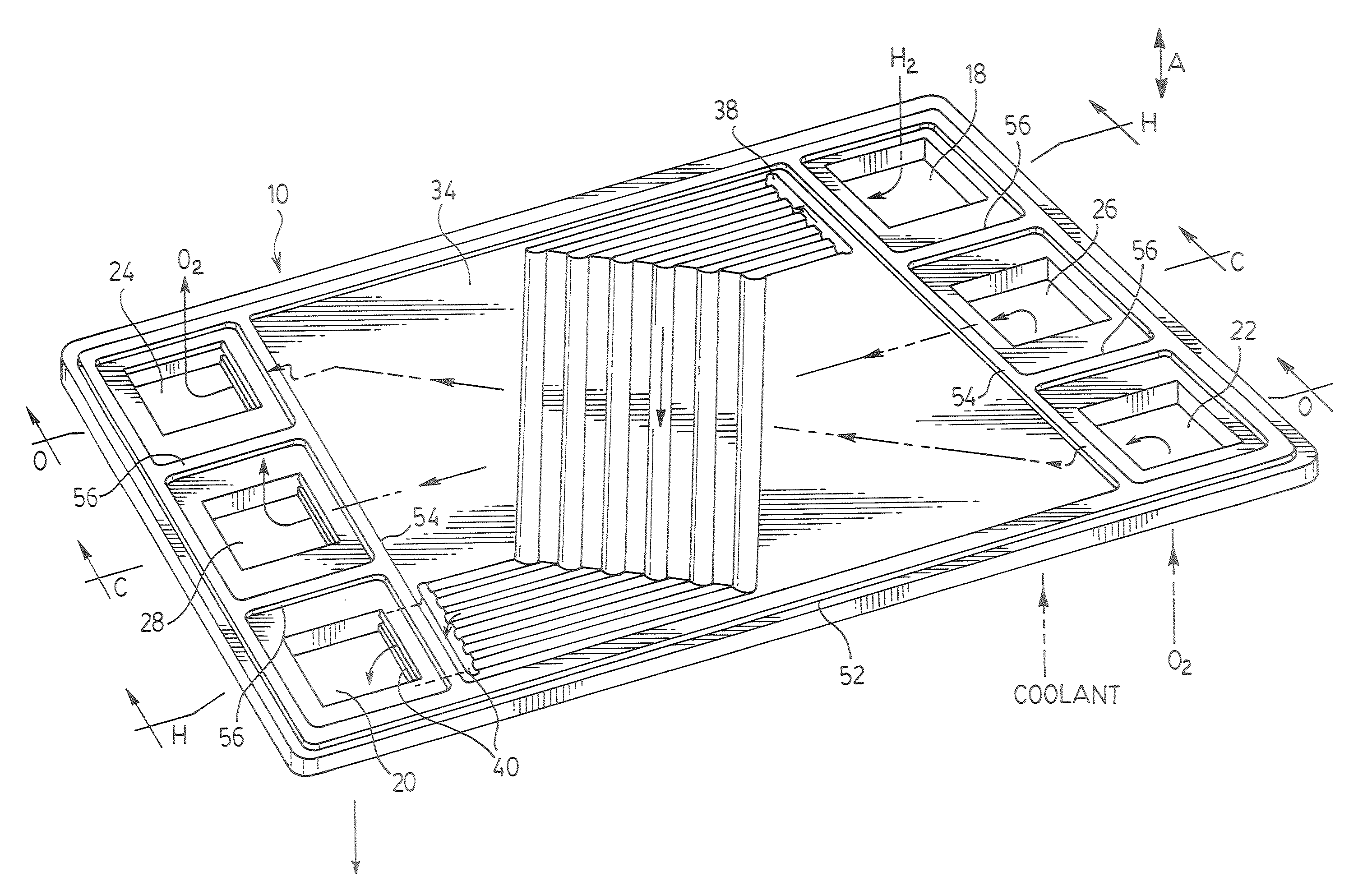
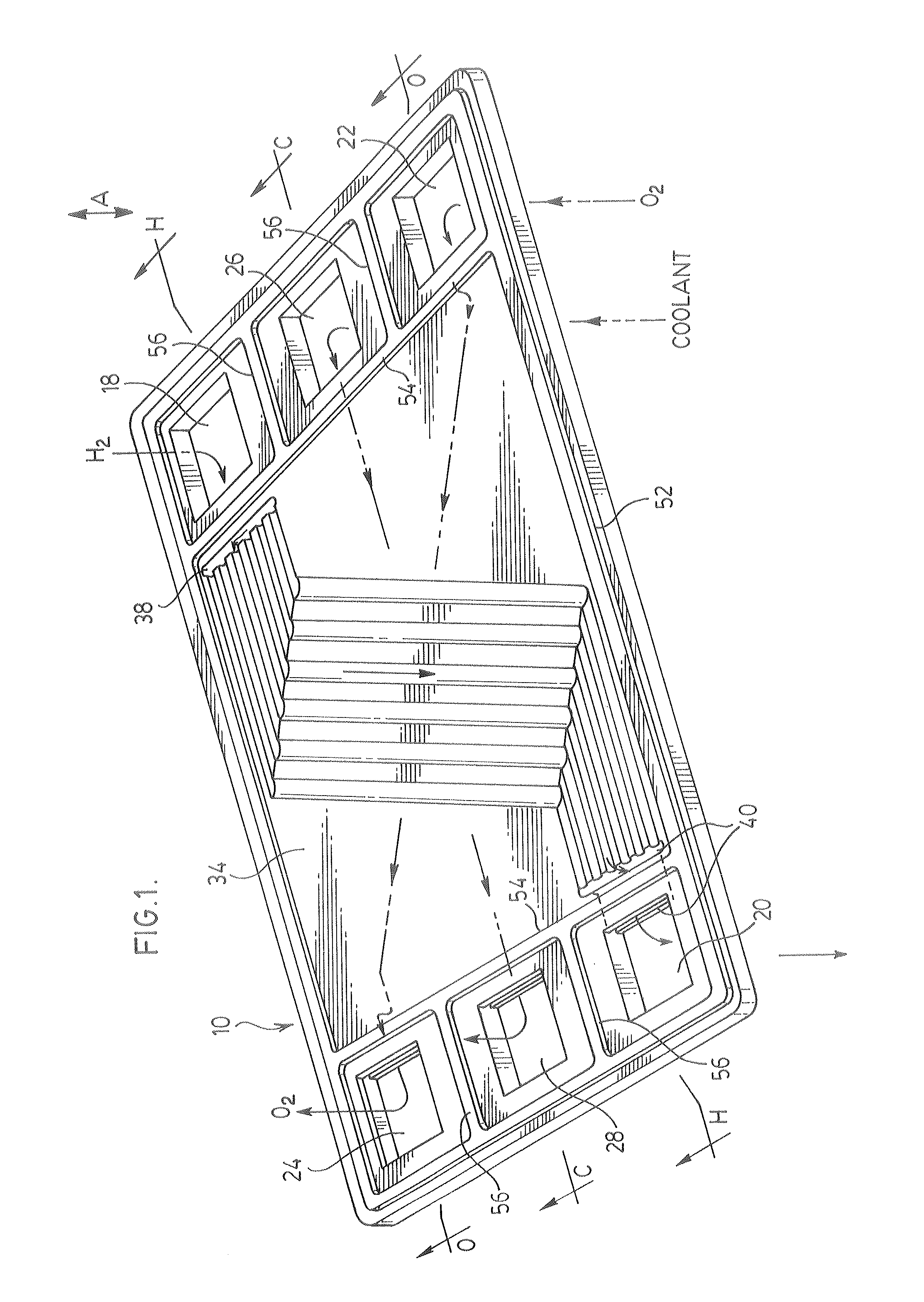
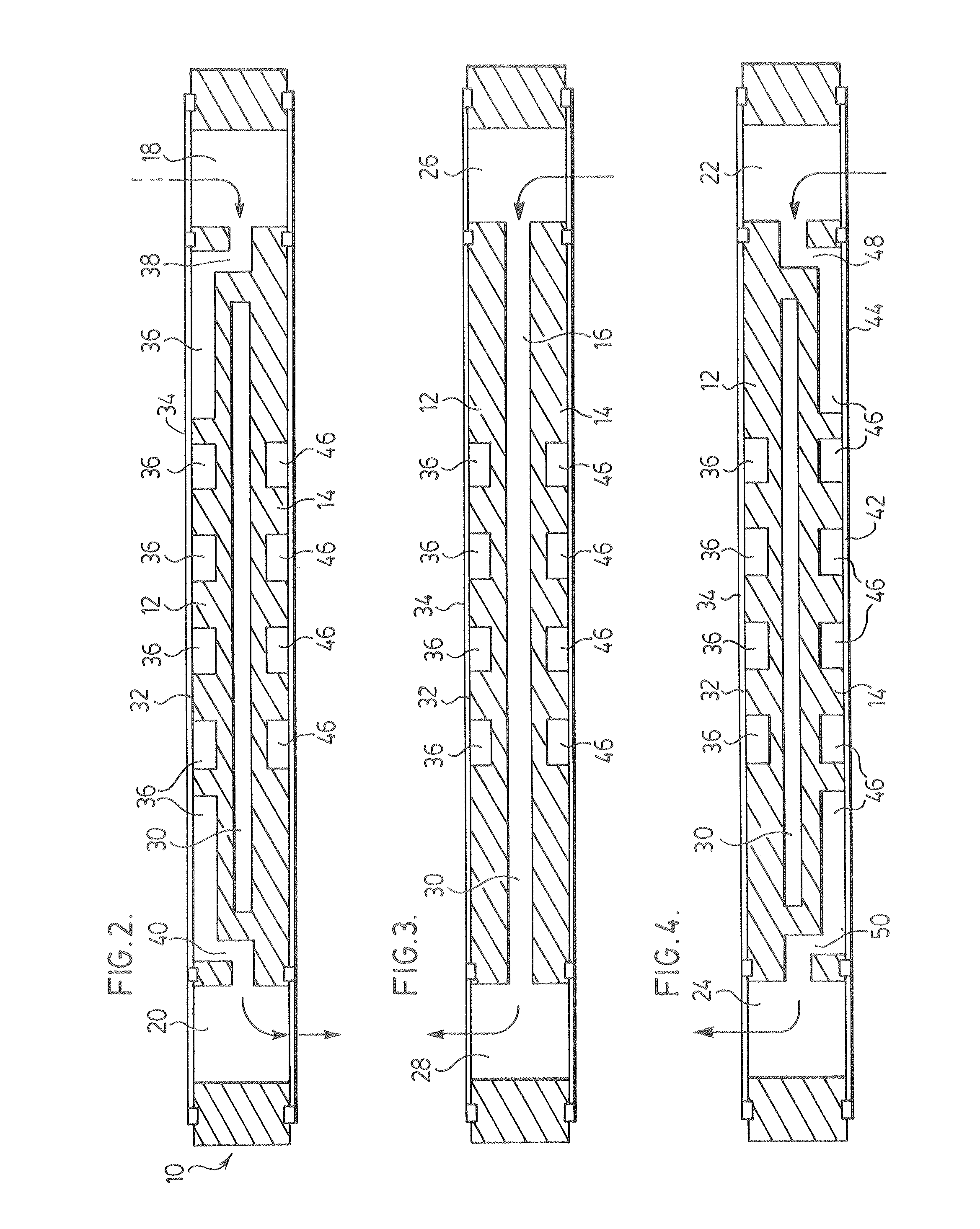
[0043]the invention is further described below with reference to FIGS. 5 to 11. The fuel cell assembly according to the first preferred embodiment of the invention includes a plurality of stacks made up of plates 10. For the purpose of simplification, FIGS. 6 to 11 omit all details of plates 10 with the exception of the inlet and outlet openings 18, 20, 22, 24, 26 and 28 and the corresponding manifolds.

[0044]As shown in FIG. 7, the fuel cell assembly includes a fuel cell stack 62 comprised a first plurality of plates 10. The identities of the inlet and outlet openings of the plates 10 in the fuel cell stack are as described above with reference to FIGS. 1 to 5. For the purpose of distinguishing the plates 10 of fuel cell stack 62 from other plates of the fuel cell assembly, they are referred to in the following description, and in FIGS. 6 to 11, by reference 10a and their openings are referred to as 18a, 20a, 22a, 24a, 26a and 28a.

[0045]The plates 10a of fuel cell stack 62 are stac...

second embodiment

[0084]FIGS. 14 to 16 illustrate in more detail the flow paths followed by the anode gas, cathode gas and the coolant as they flow through the fuel cell assembly according to the invention illustrated in FIG. 13.

[0085]It will be appreciated that the provision of multiple coolant loops and the recirculation of the anode and cathode gases in the second embodiment of the invention are two separate functions which are not necessarily embodied in a single fuel cell assembly. In a first variant of the second embodiment, illustrated in FIG. 17, multiple coolant loops are provided as in FIG. 13, but the anode and cathode gases flow through the entire fuel cell assembly from one end to the other as in the first embodiment of the invention described above.

[0086]FIG. 17 illustrates a fuel cell assembly comprising a fuel cell stack 140, a first heat exchanger 104 and a second heat exchanger 84, all of which have already been described above in detail. It will be seen from FIG. 17 that the anode ...


PUM

PropertyMeasurementUnit
electrical energyaaaaaaaaaa
heataaaaaaaaaa
operating temperatureaaaaaaaaaa

Abstract

A fuel cell assembly in which at least one heat exchanger for conditioning either the anode or cathode reactant gas is integrated with the fuel cell stack and located at the end of the fuel cell stack, to isolate the fuel cell stack from contact with the end plates of the stack. The heat exchanger may preferably be comprised of a stack of plates which may preferably be the same as the plates as the fuel cell stack, with outer and inner end plates to direct the flow of reactant gases, waste gases and coolant to and from the fuel cell stack. The assembly is preferably configured to include reactant conditioning heat exchangers at both ends of the fuel cell stack.

Description

FIELD OF THE INVENTION[0001]The invention relates to fuel cell assemblies incorporating heat exchangers to condition one or both of the anode and cathode reactant gases, and more specifically relates to fuel cell assemblies in which the reactant conditioning heat exchangers are structurally and functionally integrated with the fuel cell stack.BACKGROUND OF THE INVENTION[0002]Fuel cells are typically in the form of stacks of plates sandwiched between a pair of end plates. In a typical fuel cell, hydrogen or a hydrogen-rich gas stream is fed to the fuel cell anode and oxygen or air is fed to the fuel cell cathode. Prior to being introduced to the fuel cell stack these reactants are preferably cooled or heated to the fuel cell operating temperature by one or more heat exchangers. The heat exchangers and the fuel cell stack are typically separate components connected together by conduits. The use of separately formed heat exchangers can be problematic where space is limited and may add ...

Claims


Application Information

Patent Timeline
Patent Type & Authority Applications(United States)
IPC IPC(8): H01M8/04
CPCH01M8/04067H01M8/242H01M2008/1095Y02E60/50H01M8/2483H01M8/0267H01M8/0263
Inventor VANDERWEES, DOUG
Owner DANA CANADA CORP
Learn More