Replaceable foundation vent

a technology of foundation vents and vents, which is applied in ventilation systems, lighting and heating apparatus, heating types, etc., can solve the problems of affecting the quality of construction, and consuming valuable construction time, and achieves the effect of easy removal

Inactive Publication Date: 2009-09-24
HENDRICKS MAXWELL R
View PDF18 Cites 22 Cited by
  • Summary
  • Abstract
  • Description
  • Claims
  • Application Information

AI Technical Summary

Benefits of technology

[0008]The replaceable foundation vent comprises a mounting frame and a vent having a plurality of ventilation components, including a screen, a stationary ventilation plate, and a slider. The ventilation components are removably attachable to the mounting frame using fasteners. The mounting frame has a built-in lintel, the entire frame being adapted for mounting in an opening in a block, brick or frame foundation wall. Overhanging portions of the frame lintel rest atop foundation wall members laterally disposed on either side of the frame. Additional foundation wall members can be disposed on top of the lintel to seal off the initial top opening. Frame and vent function in the same manner as older styled unitarily constructed vents. By releasing / removing the fasteners, the ventilation components can easily be removed from the mounting frame for repairs to the vent when necessary.

Problems solved by technology

Such an installation method is accompanied by many problems in that the application of mortar around the ventilation unit perimeter may not be precise, resulting in messy residue that must be cleaned up, eating up valuable construction time.
Moreover, the application of mortar around joints requires a high degree of skill in the artisan.
The aforementioned installation method results in a permanent installation that defies easy repair or replacement, in that the mortar must be chipped away from the opening using hammer and chisel or the like.
The very process of striking at the mortar may result in inadvertent permanent damage to the ventilation unit, instead of the repair that was sought.

Method used


Image

  • Replaceable foundation vent
  • Replaceable foundation vent
  • Replaceable foundation vent

Examples


Embodiment Construction

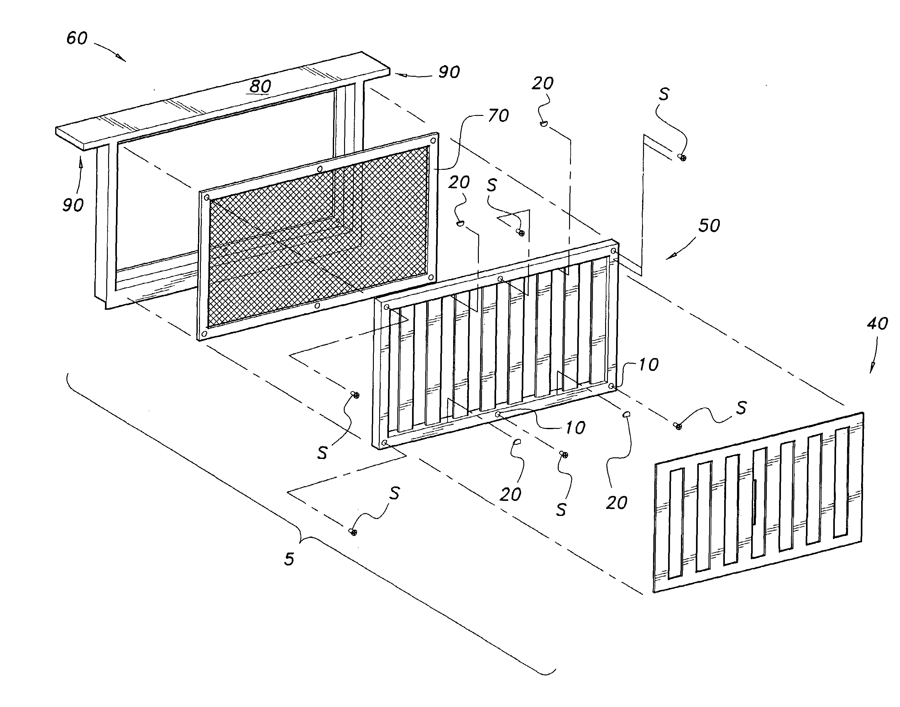
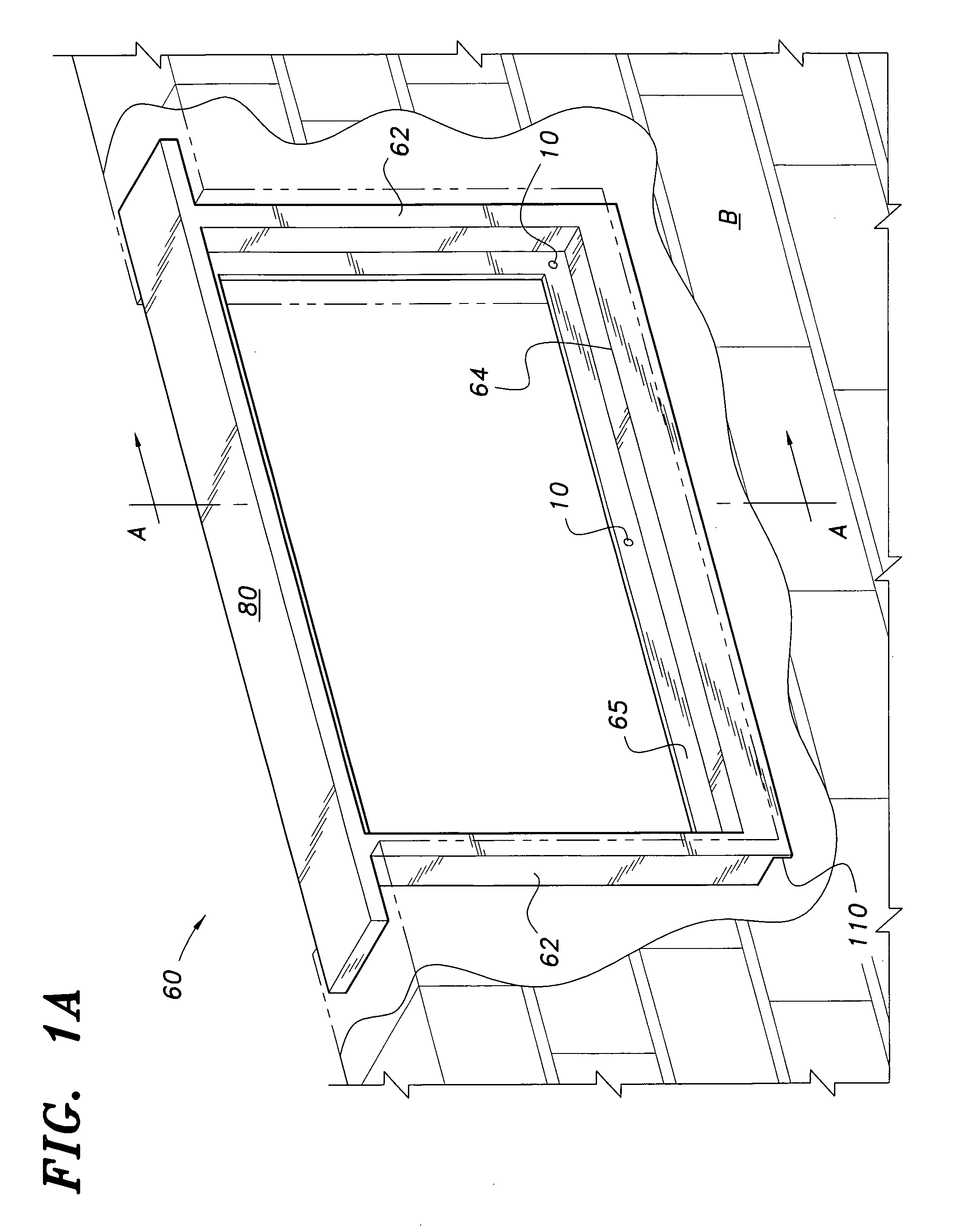
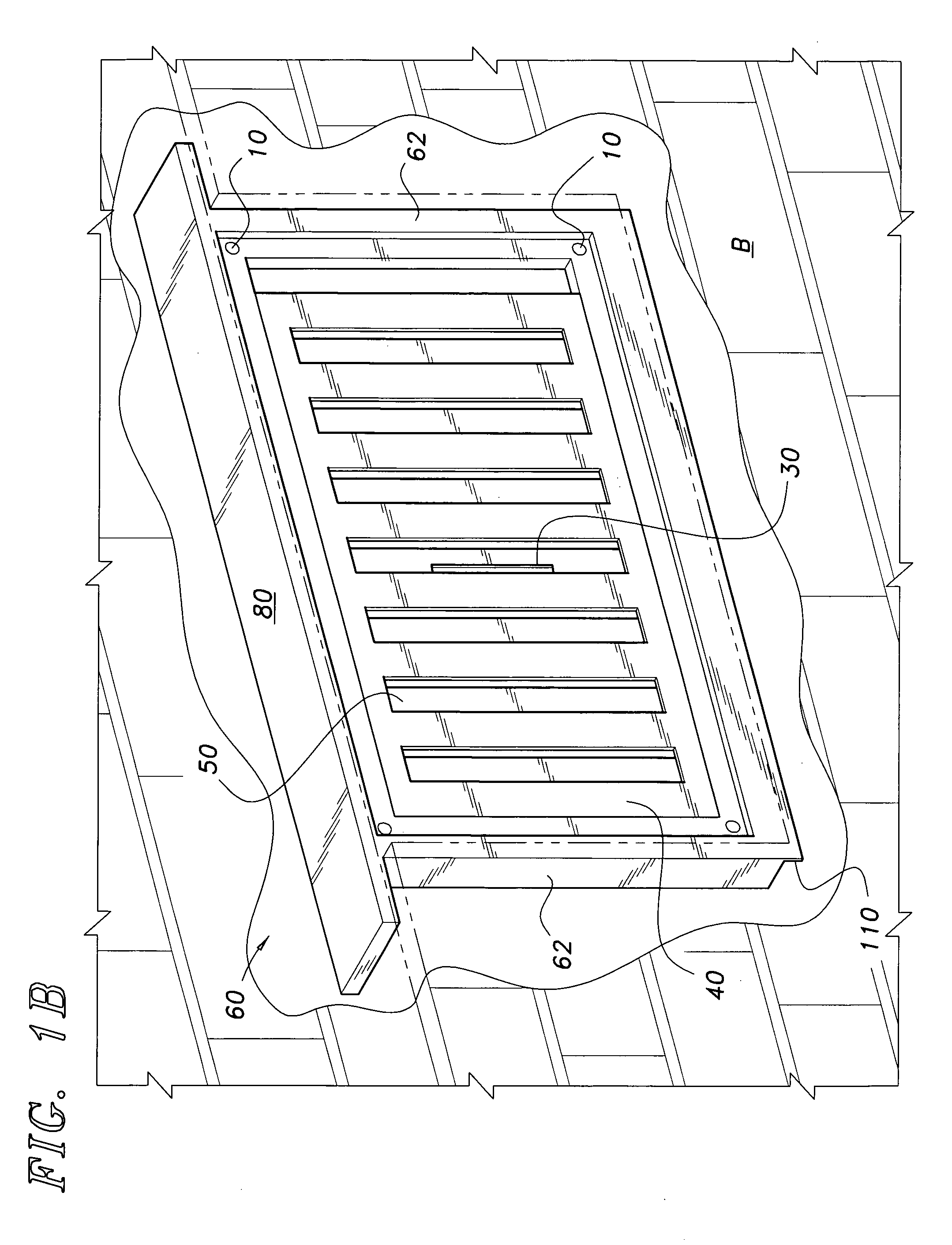
[0015]As shown in FIGS. 1A-3, the present invention relates to a replaceable foundation vent 5 that comprises a mounting frame 60, the mounting frame having respective opposing pairs of interconnected substantially horizontal and substantially vertical frame members defining a generally rectangular opening. Additionally, a plurality of vent components, including ventilation plate 50, slider panel 40, and screen 70, are removably attachable to the mounting frame 60 using fasteners, such as exemplary fasteners S. Fasteners S may be threaded, although unthreaded fasteners are also contemplated. As most clearly shown in FIGS. 1B and 2, the ventilation plate 50 and slider panel 40 are substantially rectangular, planar plates having complementary rectangular slots or gratings that allow for the regulation of airflow through the ventilation plate 50 as the slider panel 40 is slidably adjusted within the mounting frame 60. It should be understood, however, that the rectangular configuration...


PUM


Abstract

The replaceable foundation vent has a mounting frame and a plurality of vent components, including a screen, ventilation plate, and a slider. The ventilation components are removably attachable to the mounting frame using fasteners. The mounting frame has a built in lintel, the entire frame being adapted for permanent mounting in an opening in a block, brick or frame foundation wall. Overhanging portions of the frame lintel rest atop foundation wall members laterally disposed on either side of the frame. Additional foundation wall members can be disposed on top of the lintel to seal off the initial top opening. By releasing/removing the fasteners, the vent components can easily be removed from the mounting frame for repairs to the vent when necessary.

Description

BACKGROUND OF THE INVENTION[0001]1. Field of the Invention[0002]The present invention relates generally to foundation vents, and more particularly to a replaceable ventilation vent having a permanently installed mounting frame.[0003]2. Description of the Related Art[0004]Foundation ventilators are required by building codes at spaced locations for moisture control among other reasons. Such ventilators preferably include a means for opening and a means for closing the air passageway so that air flow can be increased during the warm season to minimize trapped moisture inside the foundation and air flow can be minimized during the cold season to minimize heat loss during colder periods.[0005]Foundation ventilators are usually installed in the openings provided in the foundation wall by applying mortar around the perimeter of the ventilation unit once it is positioned in the opening. Such an installation method is accompanied by many problems in that the application of mortar around the...

Claims


Application Information

Patent Timeline
Patent Type & Authority Applications(United States)
IPC IPC(8): F24F13/00
CPCF24F13/084
Inventor HENDRICKS, MAXWELL R.
Owner HENDRICKS MAXWELL R
Why Eureka
Try Eureka