Electrosurgical Generator Having Boost Mode Control Based on Impedance

Inactive Publication Date: 2009-09-24
SYNERGETICS USA
View PDF21 Cites 125 Cited by
  • Summary
  • Abstract
  • Description
  • Claims
  • Application Information

AI Technical Summary

Benefits of technology

[0014]FIG. 3 is a control circuit block schematic diagram in a

Problems solved by technology

As a result, the cutting ability of the electrosurgical tool is hindered.
This can lead to an increase in collateral damage in the tissue caused solely by the power surge.
Therefore, a cons

Method used


Image

  • Electrosurgical Generator Having Boost Mode Control Based on Impedance
  • Electrosurgical Generator Having Boost Mode Control Based on Impedance
  • Electrosurgical Generator Having Boost Mode Control Based on Impedance

Examples


Embodiment Construction

[0018]Certain terminology is used in the following description for convenience only and is not limiting. The words “right”, “left”, “lower”, and “upper” designate directions in the drawings to which reference is made. The words “inwardly” and “outwardly” refer to directions toward and away from, respectively, the geometric center of the apparatus and designated parts thereof. The terminology includes the above-listed words, derivatives thereof, and words of similar import. Additionally, the words “a” and “an”, as used in the claims and in the corresponding portions of the specification, mean “at least one.”

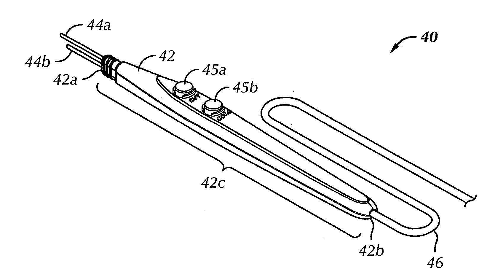
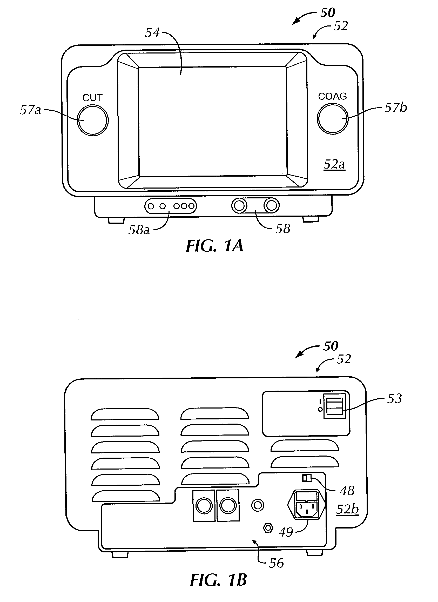
[0019]Referring to the drawings in detail, wherein like reference numerals indicate like elements throughout, there is shown in FIGS. 1A and 1B a preferred embodiment of an electrosurgical RF generator apparatus or RF generator 50. FIG. 1A is an elevational view of a front panel 52a of the RF generator 50, and FIG. 1B is a perspective view of a rear panel 52b of the RF generator 5...


PUM


Abstract

A method of controlling output power of an electrosurgical generator apparatus that controls a variable output signal to a pair of electrodes includes setting the output power of the generator apparatus to a selected power output level. An impedance is measured across the electrodes when the electrodes are applied to an area of tissue. The output power of the generator apparatus is changed to a boost power output level greater than the selected power output level. The boost power output level corresponds to a calculation based at least in part on the measured impedance. The method further includes applying the output signal to the electrodes at the boost power output level for a first time duration and changing the power output to the selected power output level after the first time duration. An electrosurgical generator apparatus operating in accordance with the method is also described.

Description

CROSS REFERENCE TO RELATED APPLICATIONS[0001]This application claims the benefit of U.S. Provisional Patent Application No. 61 / 037,794, filed on Mar. 19, 2008, entitled “Electrosurgical Generator Having Boost Mode Control Based on Impedance,” the entire contents of which are incorporated by reference herein.BACKGROUND OF THE INVENTION[0002]An embodiment of the present invention relates generally to a method of providing a boost mode in an electrosurgical generator apparatus, and more particularly, to a method of providing a boost mode wherein the boost output power level is based on a measured impedance of tissue.[0003]Devices used for controlling monopolar and bipolar electrode tools are well known in the art. U.S. Pat. No. 5,318,563, the contents of which are incorporated by reference herein, relates to electrosurgical radio frequency (RF) generators. The electrodes in the prior art systems are used for cutting and coagulation of tissue. An RF current is generated between the elec...

Claims


Application Information

Patent Timeline
IPC IPC(8): A61B18/18A61B18/12
CPCA61B18/1206A61B18/1402A61B18/1477A61B2018/00589A61B2018/00988A61B2018/00702A61B2018/00875A61B2018/00916A61B2018/00601
Inventor MALIS, JERRY L.GROCH, ANTHONY JOHN
Owner SYNERGETICS USA
Why Eureka
Try Eureka