System and method for controlling a tethered flying craft using tether attachment point manipulation

a technology of attachment point manipulation and control system, which is applied in the direction of toy aircraft, electric generator control, machines/engines, etc., can solve the problems of affecting the control of ground-based electrical generation devices, and the control surface of airborne craft may not be sufficient to maintain control of the craft, so as to achieve high tether load and high speed

Inactive Publication Date: 2011-05-26
BEVIRT JOEBEN +1
View PDF0 Cites 127 Cited by
  • Summary
  • Abstract
  • Description
  • Claims
  • Application Information

AI Technical Summary

Benefits of technology

[0010]In some aspects, the flying system is adapted to be able to use electrical energy to provide power to the generators which are used as motors to raise the system from the ground, or mounting support, into the air. The system may then be raised into a prevailing wind and use airfoils in the system to provide lift while the system is tethered to the ground. The motors may then resume operation as generators for electrical power generation.
[0011]In some aspects, the system may engage in cross-wind flight paths with high speeds and high tether loads. With the increase in tether loading, control surfaces on the airborne craft may not be sufficient to maintain control of the craft through its intended flight path. The tether attachment point to the craft may be manipulated to change the moments about the tether attach point. The manipulation may be made to account for a certain set of flight conditions, or may be made within repetitive flight path cycle.

Problems solved by technology

However, such ground based electrical generation devices are somewhat hampered by the low power density and extreme variability of natural wind currents (in time and space) at low altitudes.
In some aspects, the system may engage in cross-wind flight paths with high speeds and high tether loads.
With the increase in tether loading, control surfaces on the airborne craft may not be sufficient to maintain control of the craft through its intended flight path.

Method used


Image

  • System and method for controlling a tethered flying craft using tether attachment point manipulation
  • System and method for controlling a tethered flying craft using tether attachment point manipulation
  • System and method for controlling a tethered flying craft using tether attachment point manipulation

Examples


Embodiment Construction

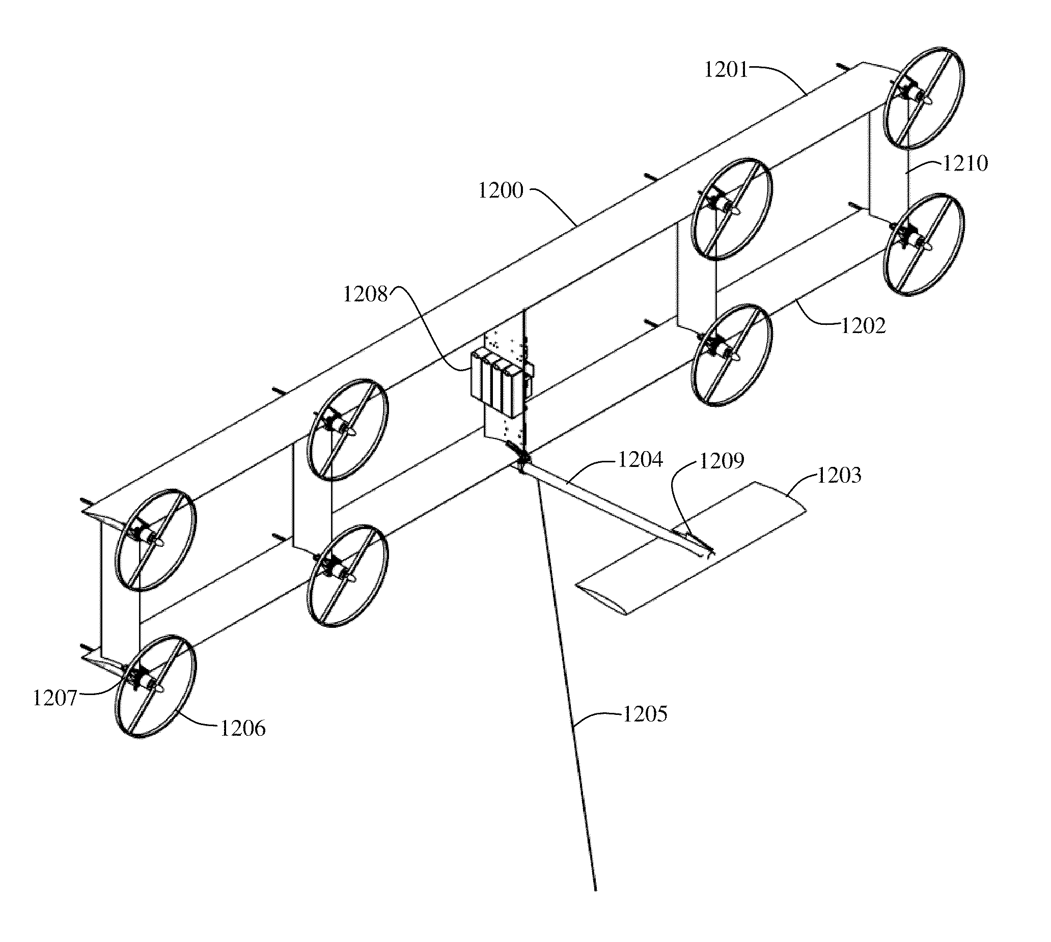
[0023]In some embodiments of the present invention, an airborne power generation system is adapted to be built in varying sizes, and to provide differing levels of power, through the use of a modular design. A strutted frame structure design with airfoil sections as part of the frame structure and with wind driven power generation turbines is adapted to be flown while tethered to a ground station. The tether may be adapted to be the structural attachment to the ground and also the electrical power conduit between the frame structure and the ground. The power generation system may be sized using modular aspects of both the structural and electrical design. In some aspects, the strutted frame structure is planar, and in other aspects the strutted frame structure may have multiple planes of struts and airfoil sections. The power generation system may be launched from the ground using vertical take-off with the assistance of ground power.

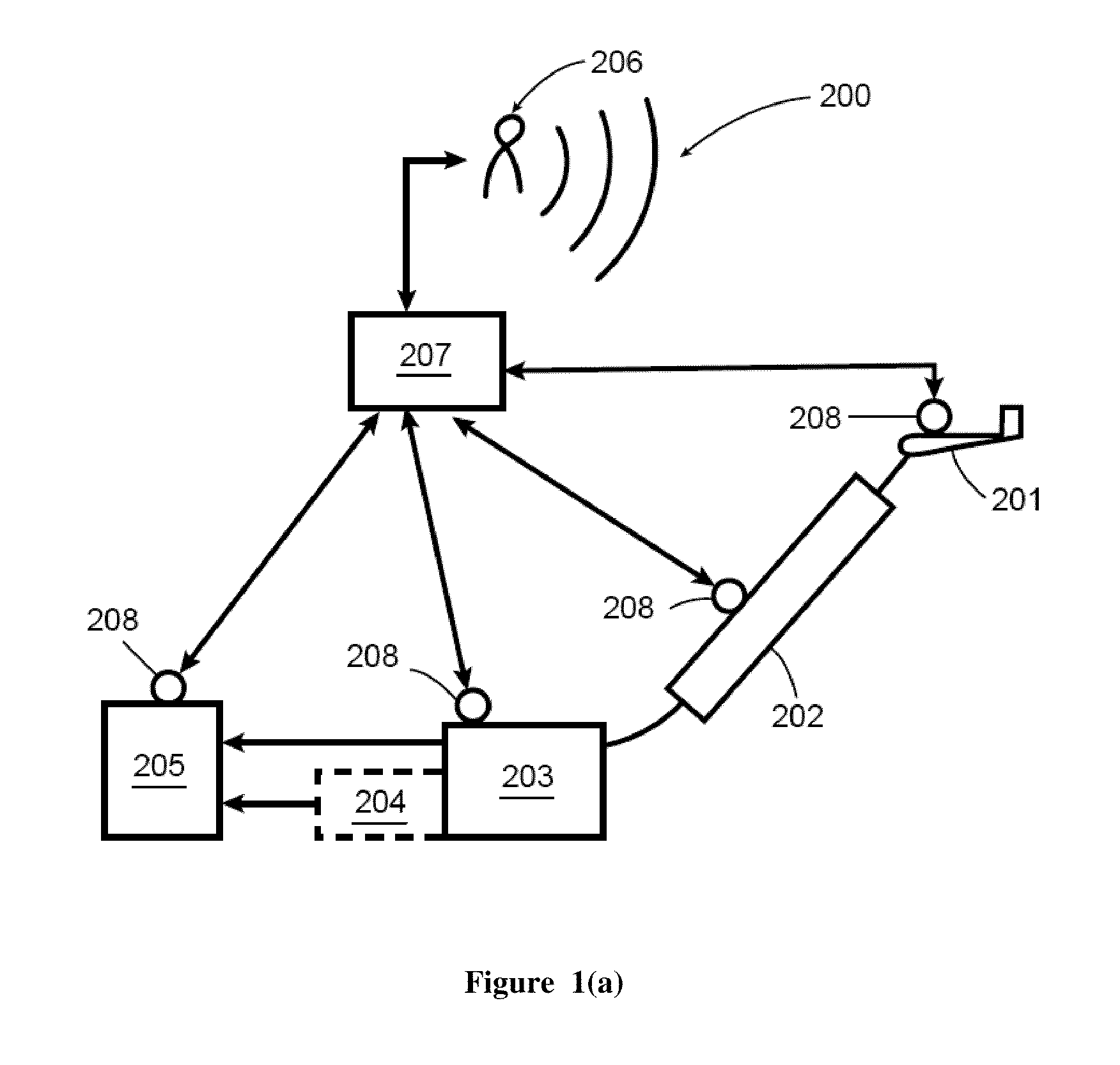
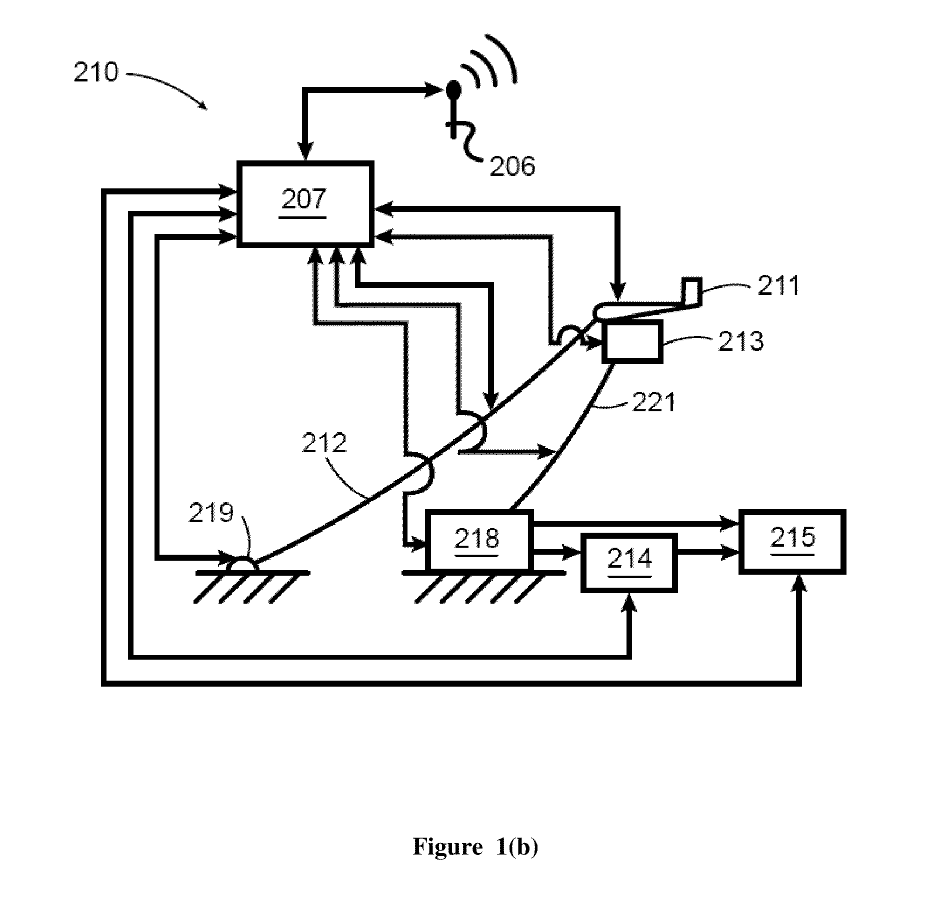
[0024]FIG. 1(a) schematically represents an examp...


PUM


Abstract

A tethered airborne electrical power generation system which may utilize a strutted frame structure with airfoils built into the frame to keep wind turbine driven generators which are within the structure airborne. The primary rotors utilize the prevailing wind to generate rotational velocity. Electrical power generated is returned to ground using a tether that is also adapted to fasten the flying system to the ground. The flying system is adapted to be able to use electrical energy to provide power to the primary turbines which are used as motors to raise the system from the ground, or mounting support, into the air. The system may use an attachment mechanism for the tether adapted to move the tether attachment point relative to the flying craft.

Description

CROSS REFERENCE TO RELATED APPLICATIONS[0001]This application is a continuation in part of U.S. patent application Ser. No. 12 / 456,694 to Bevirt, filed Jun. 19, 2009, which is hereby incorporated by reference in its entirety. This application is a continuation in part of U.S. patent application Ser. No. 12 / 459,017 to Bevirt, filed Jun. 25, 2009, which is hereby incorporated by reference in its entirety. This application claims priority to U.S. Provisional Patent Application No. 61 / 236,521 to Bevirt, filed Aug. 24, 2009, which is hereby incorporated by reference in its entirety. This application claims priority to U.S. Provisional Patent Application No. 61 / 258,177 to Bevirt, filed Nov. 4, 2009, which is hereby incorporated by reference in its entirety. This application claims priority to U.S. Provisional Patent Application No. 61 / 267,430 to Bevirt, filed Dec. 7, 2009, which is hereby incorporated by reference in its entirety.BACKGROUND[0002]1. Field of the Invention[0003]This inventi...

Claims


Application Information

Patent Timeline
Patent Type & Authority Applications(United States)
IPC IPC(8): F03D7/00F03D9/00B64C31/06
CPCF03D5/06F03D7/00F05B2240/40Y02E10/728F05B2240/921Y02E10/70Y02E10/723F05B2240/917Y02E10/72
Inventor BEVIRT, JOEBENPEDDIE, MATTHEW T.
Owner BEVIRT JOEBEN
Why Eureka
Try Eureka