Electric shears

a technology of electric shears and shears, applied in the field of electric shears, can solve the problems of unnatural operation feeling and reduced machine life, and achieve the effect of excellent operability

Active Publication Date: 2009-10-01
MAX CO LTD
View PDF9 Cites 24 Cited by
  • Summary
  • Abstract
  • Description
  • Claims
  • Application Information

AI Technical Summary

Benefits of technology

[0004]One or more embodiments of the present invention provide an electric shears ha...

Problems solved by technology

However, because a finger needs to be moved in accordance with the movement of the trigger, which moves back and forth together with the movement of the nut, th...

Method used


Image

  • Electric shears
  • Electric shears
  • Electric shears

Examples


Embodiment Construction

[0034]Hereinafter, embodiments of the present invention will be described with reference to the drawings.

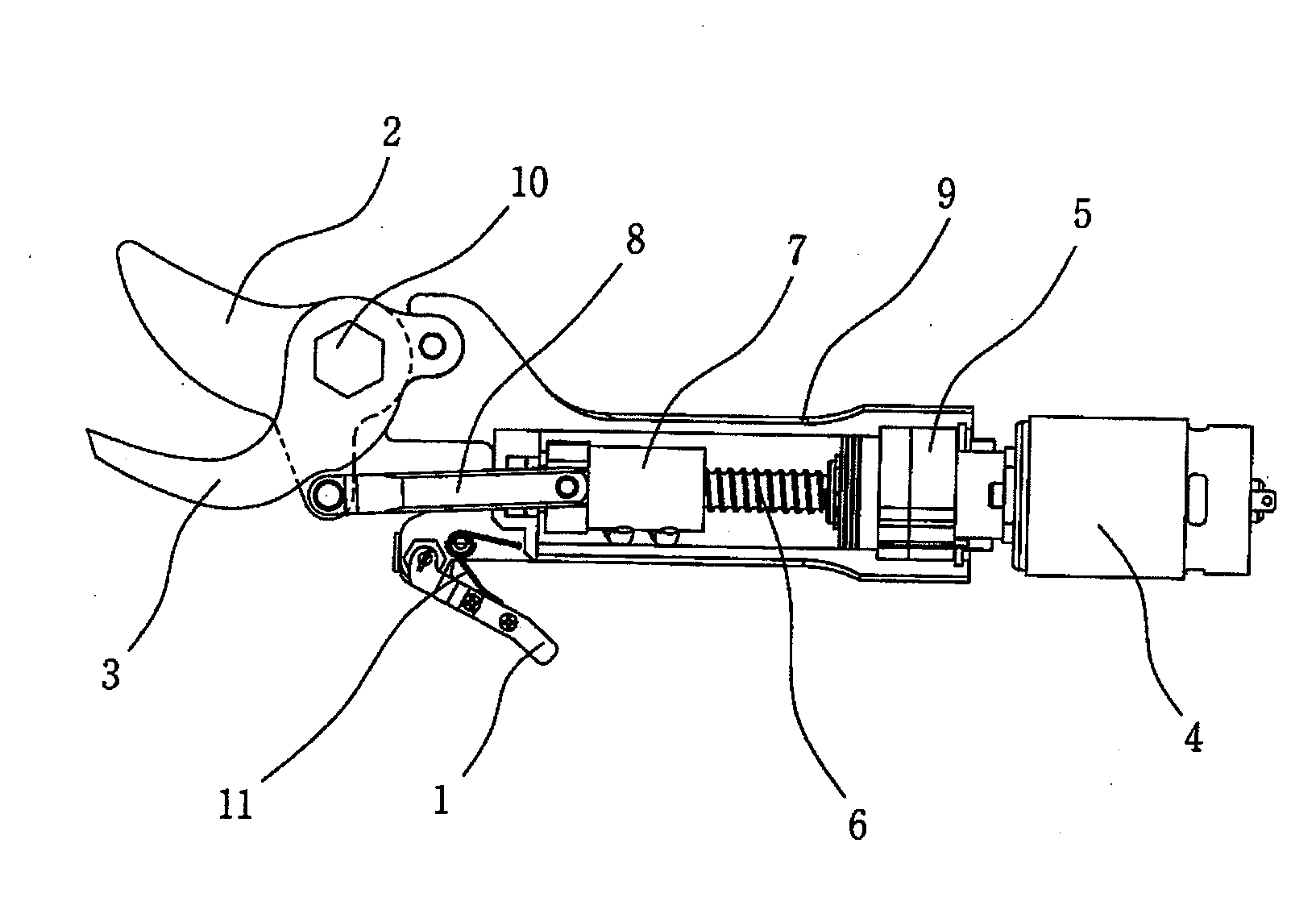
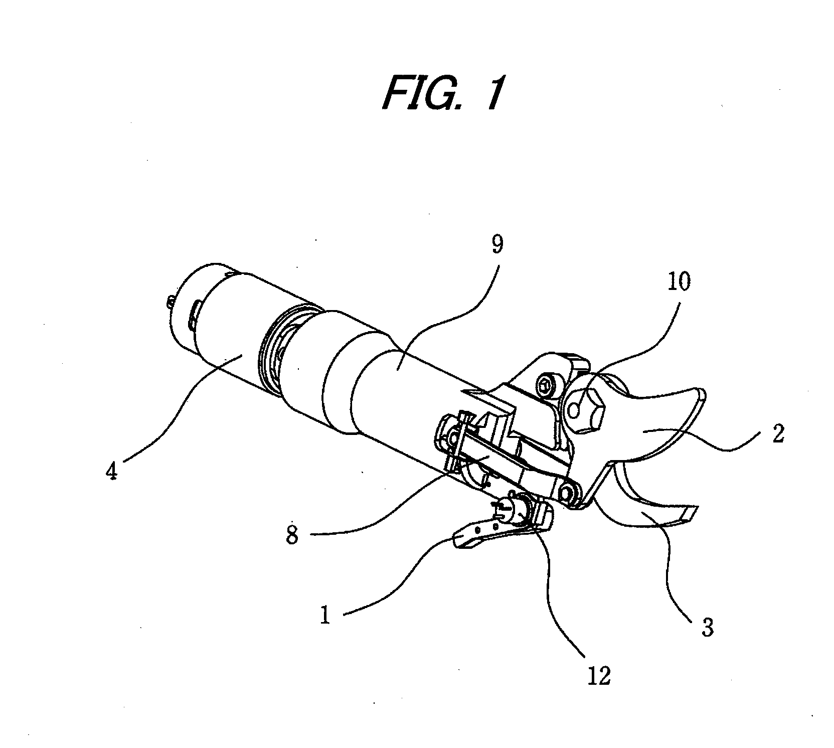
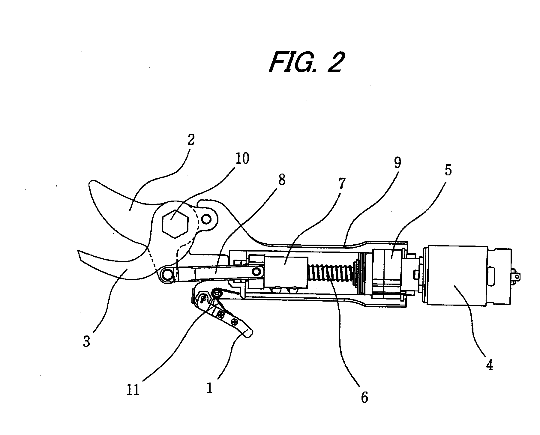
[0035]FIG. 1 illustrates a perspective view of a state in which a cover (not shown) is removed from an electric shears according to an embodiment of the invention. The electric shears is configured to move a movable blade 2 by actuating a motor 4 in accordance with a pulling operation of a trigger 1, thereby closing the movable blade 2 and a fixed blade 3 to cut an object to be cut. As illustrated in FIG. 2, the motor 4 rotates a screw shaft 6 via a speed-reducing mechanism 5 having a plurality of gears. The nut 7 is screwed onto the screw shaft 6, and slides with respect to the screw shaft 6 by rotating the screw shaft 6. A link 8 is coupled to the nut 7 at one end thereof, and is coupled to the movable blade 2 at the other end thereof. With the above configuration, when the motor 4 is forwardly and reversely rotated, the nut 7 moves back and forth inside a cylindrical frame 9, ...


PUM


Abstract

An electric shears includes a trigger operable to be pulled, a motor which rotates in accordance with a pulling operation of the trigger, a screw shaft which rotates interlockingly with the motor, a nut which is screwed onto the screw shaft and is slidable with respect to the screw shaft in accordance with a rotation of the screw shaft, a fixed blade, a movable blade which is coupled to the nut and is movable with respect to the fixed blade, a detector which detects a pulled position of the trigger, and a controller which controls a rotation of the motor based on the pulled position of the trigger detected by the detector.

Description

TECHNICAL FIELD[0001]The present invention relates to electric shears. More specifically, the present invention relates to electric shears for use in operations such as pruning in gardening, harvesting in fruit cultivation, and cutting wires, thin plates, cardboards or ropes.BACKGROUND ART[0002]Electric shears have been proposed to save labor in, for example, pruning garden trees in which a shears is manually opened and closed (see, e.g., JP 63-281680 A). The electric shears has a fixed blade and a movable blade. A cutting operation is performed by moving the movable blade with respect to the fixed blade. The movable blade is moved by a link connected to a nut that is moved back and forth in accordance with a rotation of a screw shaft. A trigger is attached to the nut. The screw shaft is rotated by a motor that is actuated by pulling the trigger, whereby the movement of the movable blade is made to interlock with the pulling operation the trigger.[0003]Accordingly, in the electric s...

Claims


Application Information

Patent Timeline
IPC IPC(8): B26B15/00
CPCB26B15/00A01G3/037A01G3/02
Inventor MANIWA, YOSHIHIROISHII, SYUICHI
Owner MAX CO LTD
Why Eureka
Try Eureka