Wall panel system including a retractable floor anchor and method

a wall panel and floor anchoring technology, applied in the direction of hinges, wing accessories, hinges, etc., can solve the problems of large door closer assemblies, time-consuming and difficult tasks, and the need for installation of door locks and rotatable bush assemblies in cavities

Active Publication Date: 2009-10-01
C R LAURENCE
View PDF22 Cites 39 Cited by
  • Summary
  • Abstract
  • Description
  • Claims
  • Application Information

AI Technical Summary

Problems solved by technology

A significant disadvantage of the anchoring mechanisms described above is that the door lock and the rotatable bush assembly must be anchored in a cavity in the floor.
As a result, if the door lock or bush is not installed during initial construction of the floor (which requires pre-planning as to the location of the wall panel assembly), an installer is required to perform the time consuming and difficult task of creating a sufficient cavity in the floor, oftentimes in concrete, and installing the assembly in that cavity.
Another disadvantage of existing systems is that the door closer assemblies are large and unsightly and are exposed either as a floor mounted assembly or as a header assembly.

Method used


Image

  • Wall panel system including a retractable floor anchor and method
  • Wall panel system including a retractable floor anchor and method
  • Wall panel system including a retractable floor anchor and method

Examples


Embodiment Construction

[0038]In the following paragraphs, the present invention will be described in detail by way of example with reference to the accompanying drawings. Throughout this description, the preferred embodiments and examples shown should be considered as exemplars, rather than as limitations on the present invention. As used herein, the “present invention” refers to any one of the embodiments of the invention described herein, and any equivalents. Furthermore, reference to various aspects of the invention throughout this document does not mean that all claimed embodiments or methods must include the referenced aspects.

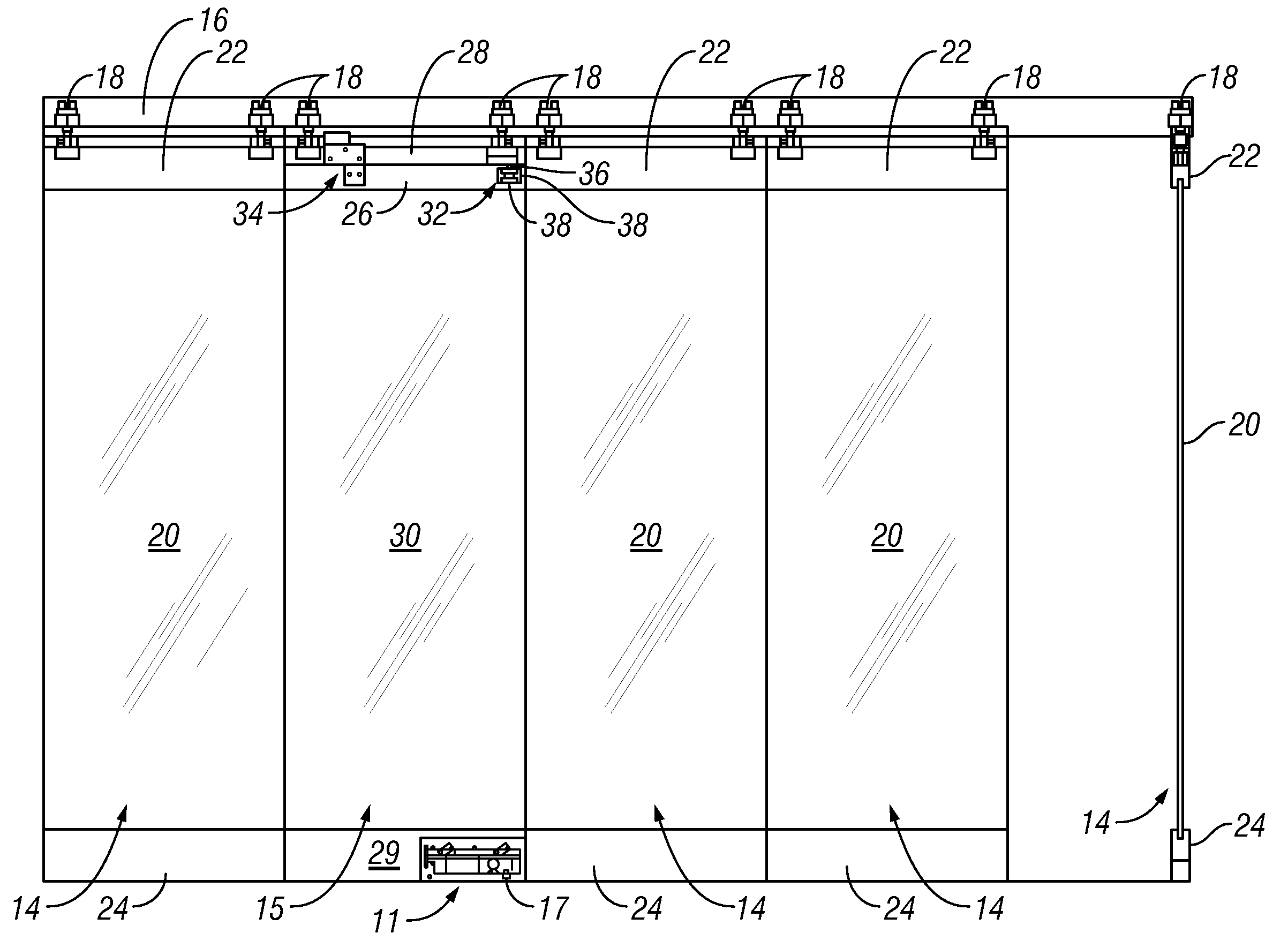
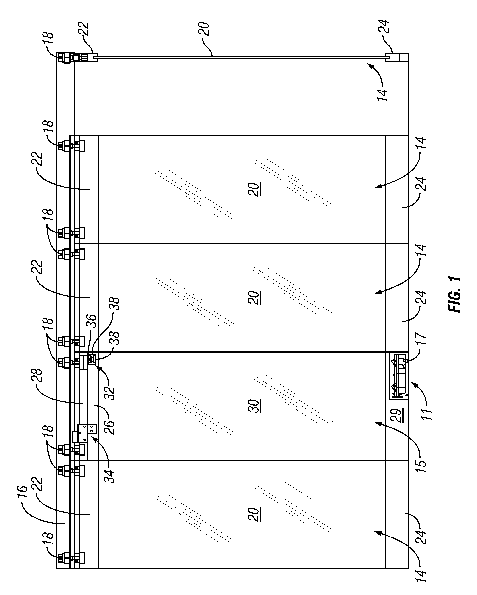
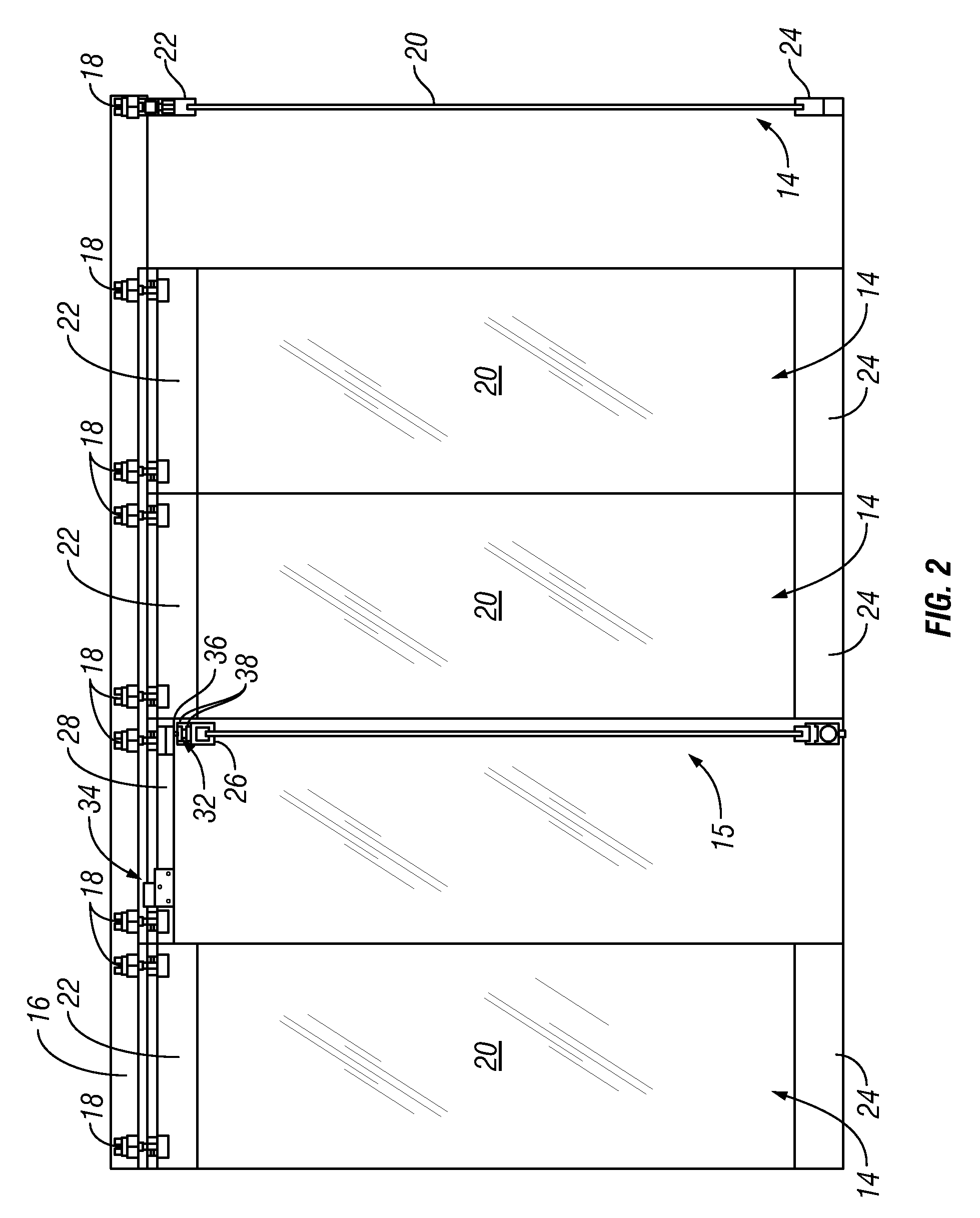
[0039]Referring first to FIGS. 1 and 2, a wall panel system 10 is described in which a floor anchor 11 of the present invention is utilized. In general, door floor anchor 11 allows a pivoting wall panel assembly 15 of wall panel system 10 to be converted between a sliding / rolling configuration and a pivoting configuration. In particular, floor anchor 11 includes retractable spi...


PUM


Abstract

A wall panel system including a retractable floor anchor for converting a wall panel assembly between a sliding configuration and a pivoting configuration. The wall panel system includes a sliding wall panel assembly and a pivoting wall panel assembly that may be configured to slide or pivot. A retractable floor anchor configured to be included in the pivoting wall panel assembly includes retractable spindle that is coupled to a base member by a linear actuator. The spindle is rotatably coupled to a door closer included in the retractable floor anchor.

Description

FIELD OF THE INVENTION[0001]The present invention relates to movable wall panel systems and, in particular, to wall panel systems that include pivoting wall panel assemblies.BACKGROUND OF THE INVENTION [0002]Movable wall panels are often used to divide an area into two or more regions. For example, movable wall panels are employed in schools, hotels, and convention centers to divide a large room into two or more smaller rooms. Another common use of movable wall panels is the formation of individual shop fronts within a mall. Clear glass panels are typically stored during business hours to produce a wide-open storefront, and are disposed in front of the storefront during off-business hours while permitting the viewing of merchandise. Alternatively, the clear glass panels maybe disposed in front of the storefront during business hours if desired, and one or more panels may be configured to pivot to provide access, for example during inclement weather.[0003]Movable wall panel systems t...

Claims


Application Information

Patent Timeline
Patent Type & Authority Applications(United States)
IPC IPC(8): E04B2/74F16H25/08E05F11/36
CPCE04B2/827E05D7/1005E05D15/58E05D2015/587Y10T74/18296E05Y2900/132E05Y2900/142E06B3/5072E06B3/924E05Y2800/672Y10T292/0844Y10T292/0867Y10T292/0971Y10T292/1015
Inventor SPRAGUE, GARY
Owner C R LAURENCE
Why Eureka
Try Eureka