Component cooling system

Inactive Publication Date: 2009-10-01
AMERICAN SUPERCONDUCTOR
View PDF10 Cites 10 Cited by
  • Summary
  • Abstract
  • Description
  • Claims
  • Application Information

AI Technical Summary

Benefits of technology

[0004]In a first implementation, a component cooling system includes a component tank configured to receive a heat-generating device. The component tank is at least partially filled with a subcooled liquid at a first pressure and at a first temperature. A cryogenic system maintains the component tank at essentially the first temperature. The cryogenic system includes a heat exchange system ther

Problems solved by technology

Unfortunately, while conduction cooling system have flexible operating temperatures, they suffer from slower recovery times.

Method used


Image

  • Component cooling system
  • Component cooling system
  • Component cooling system

Examples


Embodiment Construction

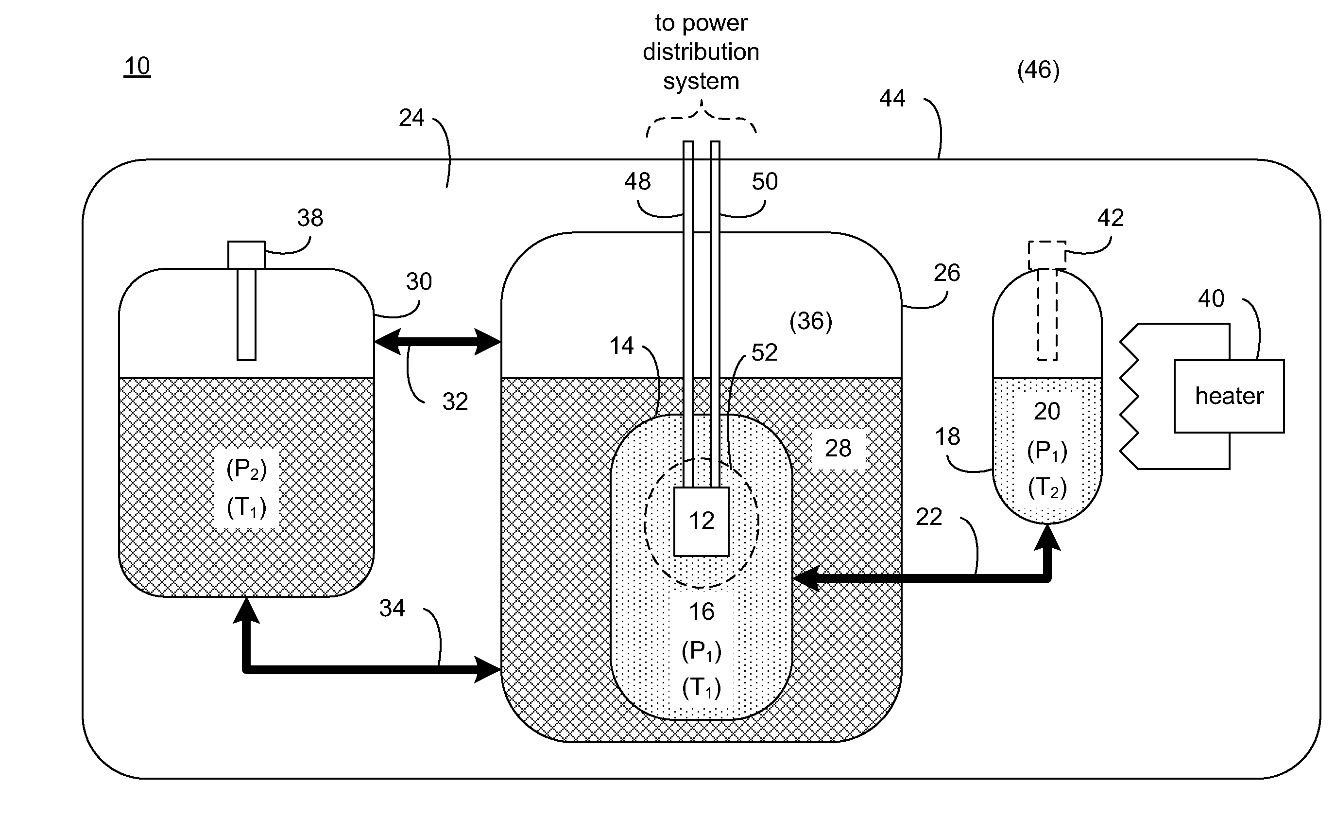
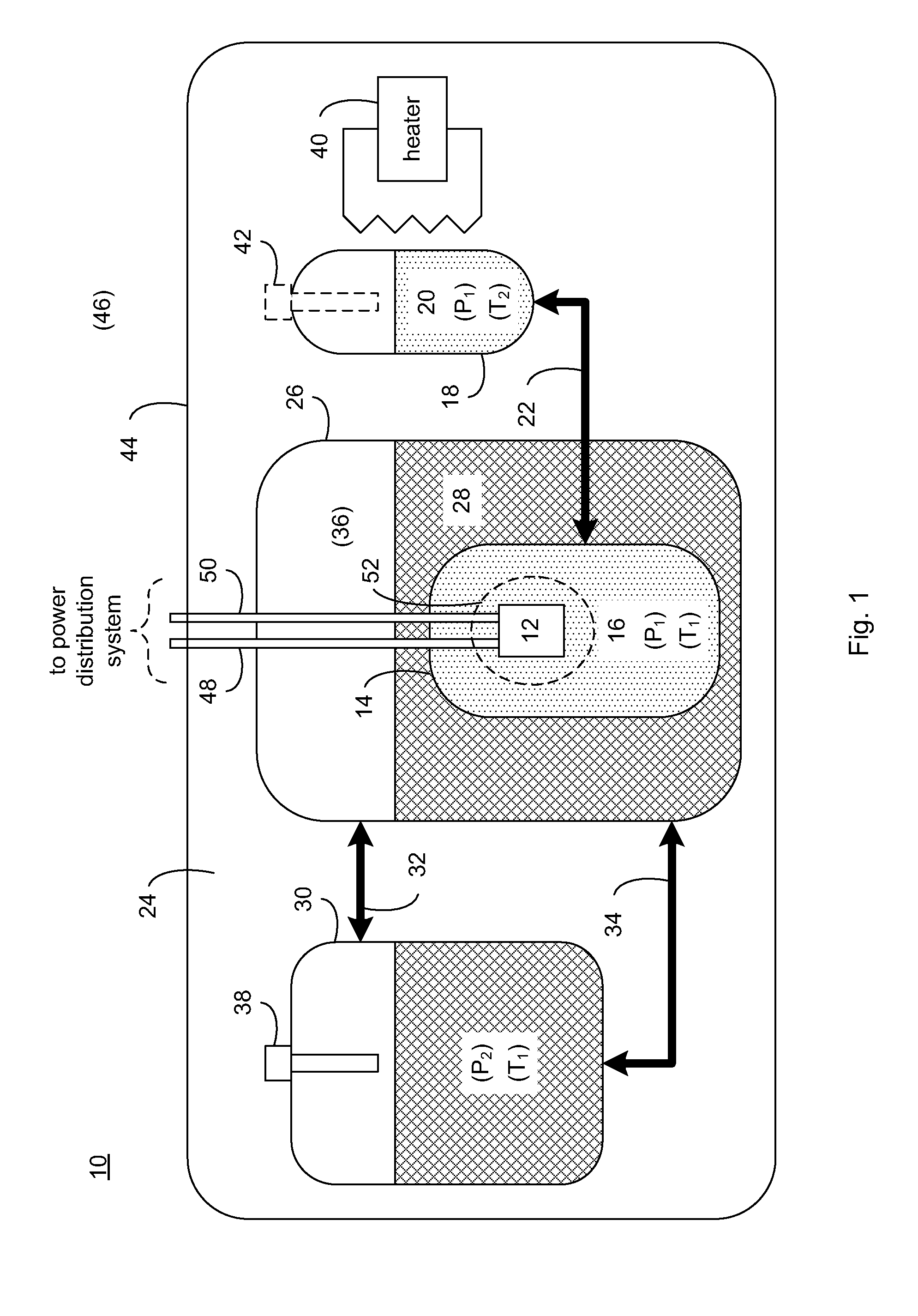
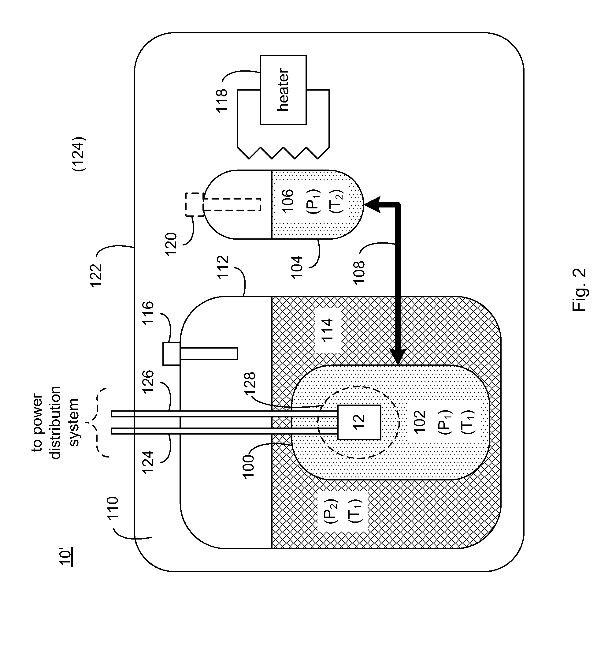
[0017]Referring to FIG. 1, there is shown a component cooling system 10 for absorbing thermal energy generated by heat-generating device 12. Examples of heat-generating device 12 may include, but are not limited to, HTS fault current limiters, a resistive electrical device, and a heat-generating mechanical device. A fault current limiter is a device that reduces the amplitude of a surge current within an electrical system that may occur due to e.g., the energizing / deenergizing of various portions of a power grid, electrical / mechanical failures within a power grid, lightening strikes, and storm damage.

[0018]A fault current limiter may be constructed using superconductor tapes or wires. When designing a fault current limiter, the superconductor windings (such as those made from high-temperature or low-temperature superconductor material) may be configured such that the impedance of the fault current limiter is negligible when subjected to normal current loads. However, when exposed to...


PUM


Abstract

A component cooling system includes a component tank configured to receive a heat-generating device. The component tank is at least partially filled with a subcooled liquid at a first pressure and at a first temperature. A cryogenic system maintains the component tank at essentially the first temperature. The cryogenic system includes a heat exchange system thermally coupled with at least a portion of the component tank. The heat exchange system is at least partially filled with a second saturated liquid at a second pressure and at essentially the first temperature. A cryostat tank is fluidly-coupled with the heat exchange system and allows for pumpless displacement of the second saturated liquid between the heat exchange system and the cryostat tank.

Description

TECHNICAL FIELD[0001]This disclosure relates to cooling systems and, more particularly, to cryogenic cooling systems for high temperature superconductor (“HTS”) devices, in particular HTS fault current limiters (“FCL”).BACKGROUND[0002]High temperature superconductors may be used to construct superconducting FCLs, which control or limit fault currents within electric power distribution systems. Cryogenic cooling systems (e.g., conduction cooling systems, saturated nitrogen cooling systems, and subcooled nitrogen cooling systems with helium gas) are often used to maintain the HTS windings within the FCL at cryogenic temperatures required for the HTS to operate in a superconducting state even during periods of impulsive heating generated by fault currents in the system and experienced by the fault current limiter.[0003]Unfortunately, while conduction cooling system have flexible operating temperatures, they suffer from slower recovery times. Further, while saturated nitrogen cooling sy...

Claims


Application Information

Patent Timeline
IPC IPC(8): F25B19/00
CPCF25B2400/01H01F6/04F25D19/006F25B2400/17
Inventor YUAN, JIEMAGUIRE, JAMES
Owner AMERICAN SUPERCONDUCTOR
Why Eureka
Try Eureka