Superconducting device having a cryogenic system and a superconducting switch

a superconducting switch and superconducting device technology, applied in the direction of superconducting magnets/coils, magnetic bodies, pulse techniques, etc., can solve the problems of continuous heating of the switching path in the activated/resistive state, effectively limited cooling power that can be transferred to the switch,

Inactive Publication Date: 2007-03-22
SIEMENS AG
View PDF11 Cites 13 Cited by
  • Summary
  • Abstract
  • Description
  • Claims
  • Application Information

AI Technical Summary

Benefits of technology

[0007] It is one possible object of the present invention to configure the superconducting device with the features mentioned at the beginning t

Problems solved by technology

On the other hand, the cooling power that can be transferred to the switch can be effectively limited by selecting the cross section of the pipeline in the region of its constriction, this being done by reducing the heat flux from the a

Method used


Image

  • Superconducting device having a cryogenic system and a superconducting switch
  • Superconducting device having a cryogenic system and a superconducting switch
  • Superconducting device having a cryogenic system and a superconducting switch

Examples


Embodiment Construction

[0029] Reference will now be made in detail to the preferred embodiments of the present invention, examples of which are illustrated in the accompanying drawings, wherein like reference numerals refer to like elements throughout.

[0030] Corresponding parts are provided with the same reference numerals in the figures.

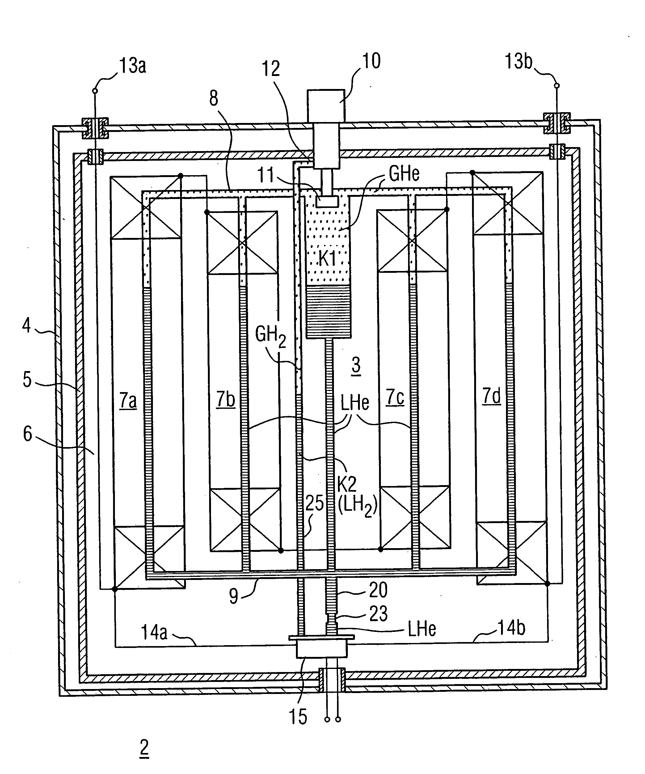
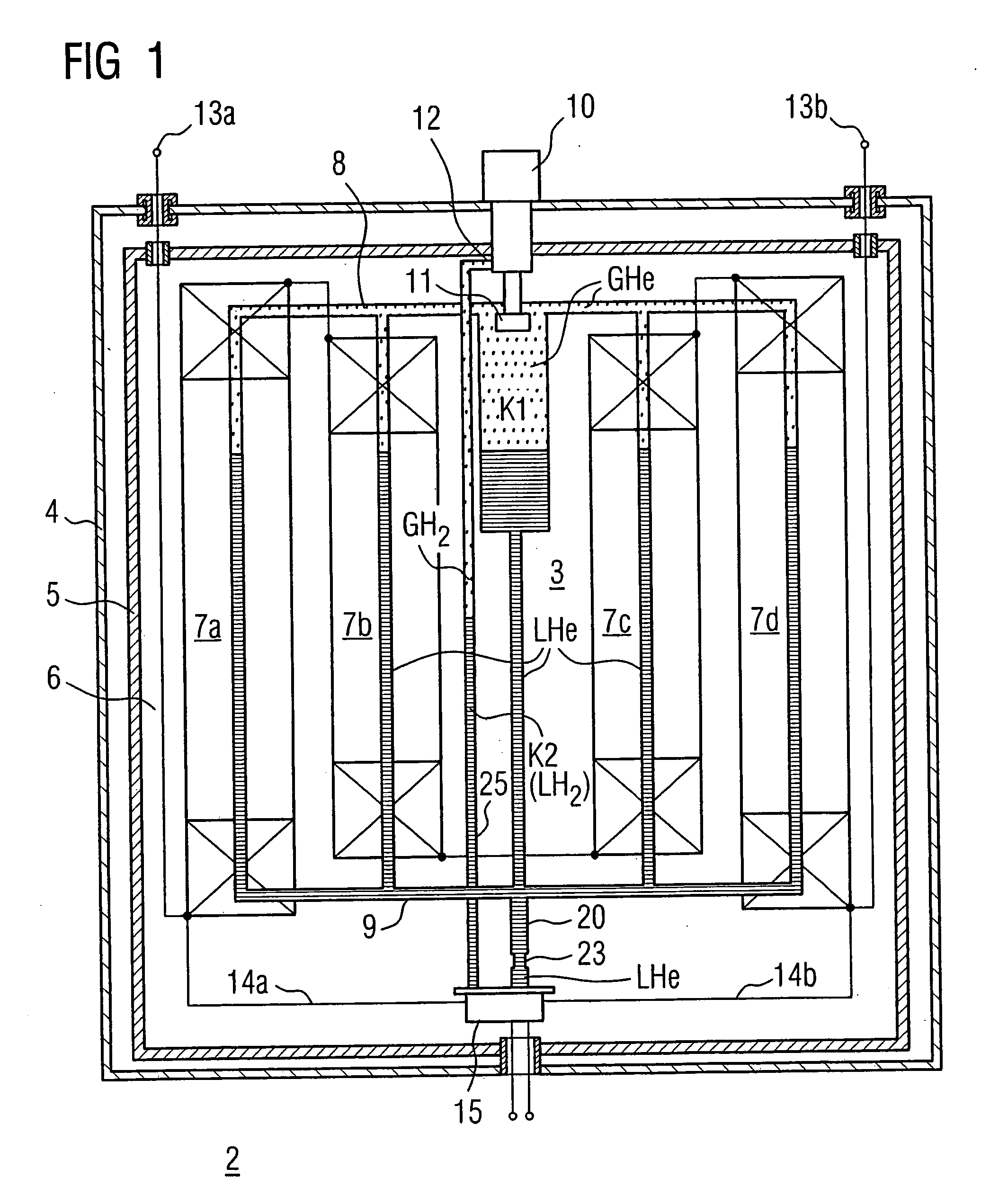
[0031] The cryogenic system designed can be provided per se for any desired devices in superconducting technology that require at least one superconducting switch for the at least one superconducting unit thereof. The superconducting units or apparatuses can be, for example, a magnet, a machine or a transformer; a superconducting cable is also possible. The superconducting unit is preferably an MRI magnet or a corresponding magnet system that is to be short circuited for the operating state by at least one superconducting permanent current switch. The following may be taken to proceed from such an exemplary embodiment.

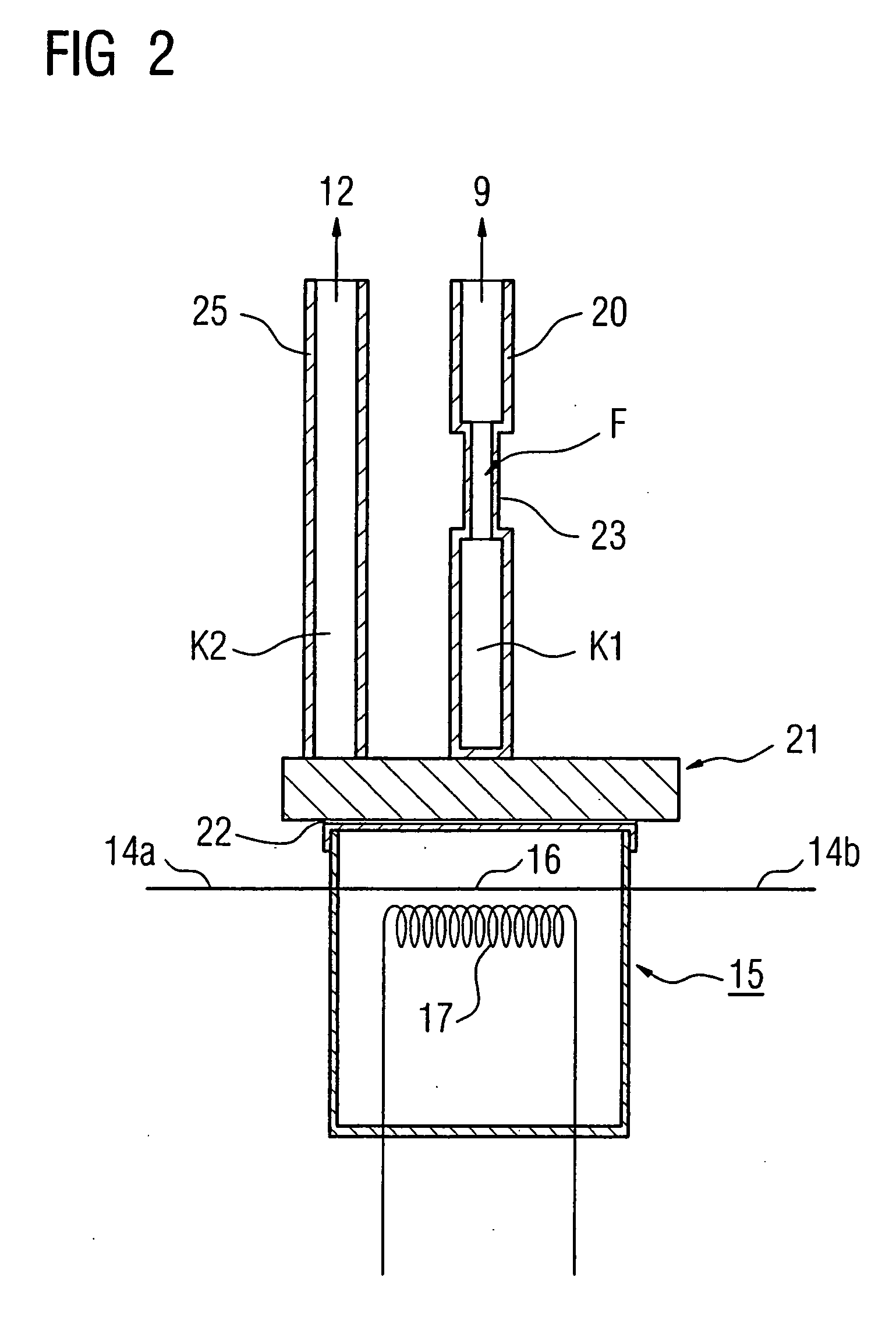
[0032] The superconducting device denoted in genera...


PUM


Abstract

The superconducting device has a cryogenic system to whose first refrigerant there is thermally coupled a superconducting unit and a superconducting switching path, which is electrically connected to said unit and is to be activated thermally by a heater, of a superconducting switch. A first pipeline to whose end the superconducting switching path is thermally coupled is to be connected to a refrigerant space of the superconducting unit. In order to ensure reliable heating of the switching path upon activation of the heater, the first pipeline is to have a cross sectional constriction impeding the exchange of heat with the refrigerant space. Moreover, the switching path is to be thermally coupled to a comparatively higher temperature level via a further, closed pipeline with a second refrigerant.

Description

CROSS REFERENCE TO RELATED APPLICATIONS [0001] This application is based on and hereby claims priority to German Application No. 10 2004 058 006.5 filed on Dec. 1, 2004, the contents of which are hereby incorporated by reference. BACKGROUND OF THE INVENTION [0002] The invention relates to a superconducting device having a cryogenic system to whose cryogenic medium to be cooled by a cooling plant are thermally coupled [0003] the superconductors of at least one superconducting unit and [0004] the superconducting switching path, electrically connected to these superconductors, of a superconducting switch, the superconducting switching path being assigned a heater for a controlled transition of the superconducting material of the switching path into the normally conducting state. A corresponding superconducting device having such a cryogenic system is to be gathered from EP 0 074 030 A2. [0005] In the case of superconducting switches, the physical effect of the controllable transition...

Claims


Application Information

Patent Timeline
IPC IPC(8): F17C3/10F25B19/00
CPCF17C2270/0527H03K17/92H01L39/20H10N60/355H01F6/00H01F27/40H10N60/30
Inventor HASSELT, PETER VAN
Owner SIEMENS AG
Why Eureka
Try Eureka