Cryogenic system with rapid thermal cycling

a cryogenic system and rapid technology, applied in the direction of domestic cooling apparatus, container discharge methods, superconducting magnets/coils, etc., can solve the problems of temperature oscillation, low cooling efficiency, and low cooling efficiency of the system, so as to reduce the available cooling power, slow down the cooling process, and accelerate the cooling process

Inactive Publication Date: 2012-04-26
HYPRES
View PDF4 Cites 11 Cited by
  • Summary
  • Abstract
  • Description
  • Claims
  • Application Information

AI Technical Summary

Benefits of technology

[0023]In addition to gas flow associated with the deliberate temperature excursions as described above, there will also be some gas flow associated with the “ac” temperature oscillations, at the cyclic frequency of order 1 Hz. This ac gas flow between the cold gas container and the room-temperature reservoir will transfer heat from the reservoir to the container during the cooling part of each cycle. While the amplitude of these temperature oscillations may be significantly reduced by the thermal damper, and hence the heat transferred per cycle will be small, the high frequency can lead to a significant average heat load on the container. This can reduce the availa

Problems solved by technology

However, the thermal damper functions to slow down the cooling response of the system which is undesirable in applications where it is desirable and/or necessary to have rapid cycling between two different (cryogenic) temperature levels.
A problem with the cryocooler system of FIG. 1A is that it is operated with a low frequency cyclic process (e.g., on the order of 1 Hz) which in turn causes the cooling power to oscillate/vary at this frequency.
In many applications, such as for cooling superconducting devices (e.g., device 226 in FIGS. 1A and 2) which have a strong temperature dependence, these temperature oscillations (e.g., of about 0.3K) are problematic since they may cause malfunctions of the devices.
Variations/oscillations about the value of Td, even if relatively small, are undesirable because the operation of the devic

Method used


Image

  • Cryogenic system with rapid thermal cycling
  • Cryogenic system with rapid thermal cycling
  • Cryogenic system with rapid thermal cycling

Examples


Embodiment Construction

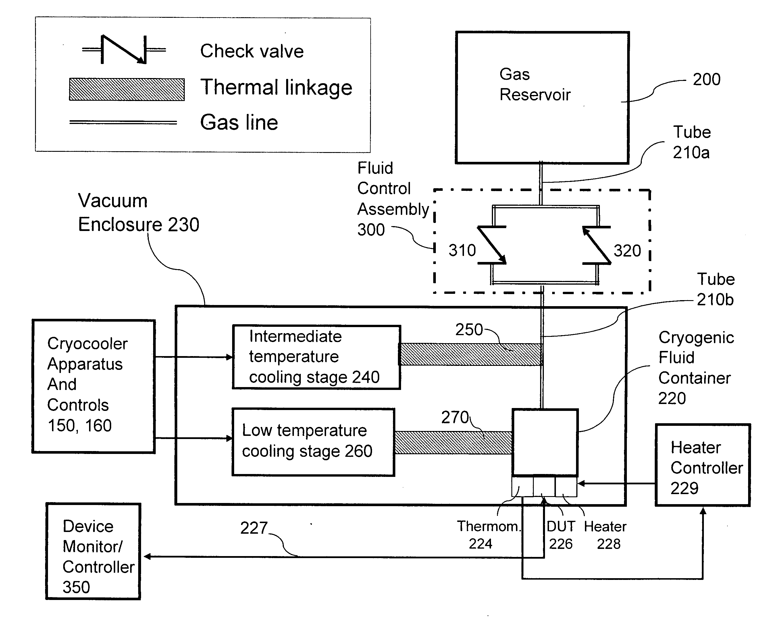
[0034]FIG. 3 shows that, in systems embodying the invention, the prior art thermal damper system consisting of a gas reservoir 200 and a cryogenic container 220 is modified with a fluid control assembly (e.g., 300) to provide improved cool down performance when the cryo container is subjected to thermal cycling. As shown in FIG. 3, a fluid control assembly (e.g., 300) inserted in the gas / fluid line connecting a cryogenic container (e.g., 220) with a gas reservoir (e.g., 200).

[0035]Reservoir 200, designed to hold a volume of gas (e.g., He), is typically maintained at room temperature. It is coupled via a first tube 210a, (which may also be denoted as a conduit, (which need not be a capillary tube) to one side (arbitrarily also referred to as the “top” side) of a fluid control assembly 300. The other side (arbitrarily referred to as the “bottom” side) of fluid control assembly 300 is coupled via a second tube 210b (which may also be denoted as a conduit) to container 220 which is suit...


PUM


Abstract

A fluid control assembly is connected between a cold gas container intended to be operated at deep cryogenic temperatures (e.g., 4K) and a gas reservoir for controlling the flow of fluid between the container and the reservoir. The fluid control assembly may be a passive valve assembly or an electrically controlled valve assembly which controls fluid flow between the reservoir and the container as a function of temperature and/or pressure differentials. The fluid control assembly enables the container to be rapidly cooled by restricting the amount of fluid flow from the reservoir into the container when the container is subjected to thermal cycling within a limited temperature range (e.g., 4K to 11K). The fluid control assembly together with the gas reservoir and the container form a thermal damper which is suited for use in a cryocooling system for producing the cryogenic temperatures (e.g., 4K) to operate superconducting devices which may need to be thermally cycled to remove trapped flux.

Description

BACKGROUND OF THE INVENTION[0001]This invention relates to apparatus and methods for providing highly stable deep cryogenic temperatures and for enabling rapid thermal cycling at cryogenic temperatures.[0002]Suitable apparatus for providing deep cryogenic temperatures include cryogenic refrigerators, also referred to as cryocoolers. To attain temperatures near absolute zero degrees Kelvin, a known available working cooling fluid is helium (He). The term “cooling fluid” as used herein refers to the working coolant (e.g., He) whether in a liquid, gaseous or any intermediate state and “degrees Kelvin” may be denoted herein by the capital letter “K”.[0003]A variety of different thermodynamic approaches are used in commercial helium-cycle cryocoolers, including Gifford-McMahon (GM), pulse tube, and Stirling cycles. See, for example, “Cryocoolers: The State of the Art and Recent Developments”, R. Radebaugh, J. Physics Condensed Matter, vol. 21, 164219 (2009).[0004]Known cryocoolers of the...

Claims


Application Information

Patent Timeline
IPC IPC(8): F17C7/00F25B19/00
CPCF25D19/006H01F6/04F25D2400/02
Inventor WEBBER, ROBERT J.DELMAS, JEAN
Owner HYPRES
Why Eureka
Try Eureka