Cryogenic system

a cryogenic system and cryogenic technology, applied in the field of cryogenic systems, can solve problems such as polluting the refrigerator sleeve, and achieve the effect of preventing air from entering and ensuring replacemen

Active Publication Date: 2008-07-08
KOBE STEEL LTD
View PDF9 Cites 10 Cited by
  • Summary
  • Abstract
  • Description
  • Claims
  • Application Information

AI Technical Summary

Benefits of technology

[0018]In order to solve the above problems, it is an object of the present invention to provide a cryogenic system in which a refrigerator can be readily replaced in such a manner that air is prevented from entering a refrigerator sleeve.

Problems solved by technology

During this operation, air and / or moisture of which the volume is equal to that of the refrigerator enters the refrigerator sleeve from outside to cause pollution in the refrigerator sleeve.

Method used


Image

  • Cryogenic system
  • Cryogenic system
  • Cryogenic system

Examples


first embodiment

[0051]the present invention will now be described with reference to drawings.

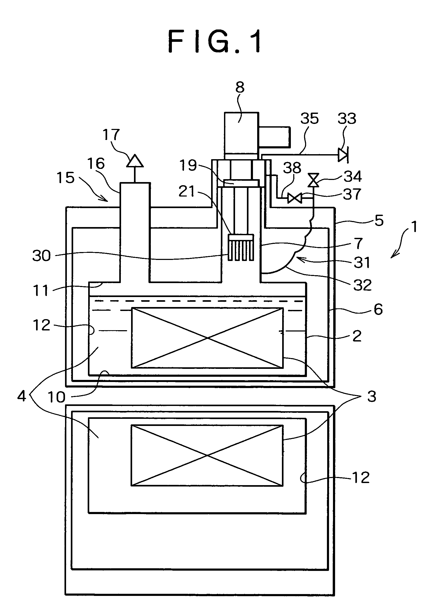
[0052]FIG. 1 is a schematic sectional view of MRI which is an example of a cryogenic system.

[0053]The cryogenic system 1 includes a containment vessel 2. The containment vessel 2 contains a superconducting magnet 3 that is a body to be cooled, the body being immersed in a liquid coolant 4 that is liquid helium. The containment vessel 2 is surrounded by a vacuum vessel 5 with a space present therebetween and the space is maintained under vacuum. A thermal shield 6 is placed in the space between the containment vessel 2 and the vacuum vessel 5 in such a manner that the thermal shield 6 surrounds the containment vessel 2.

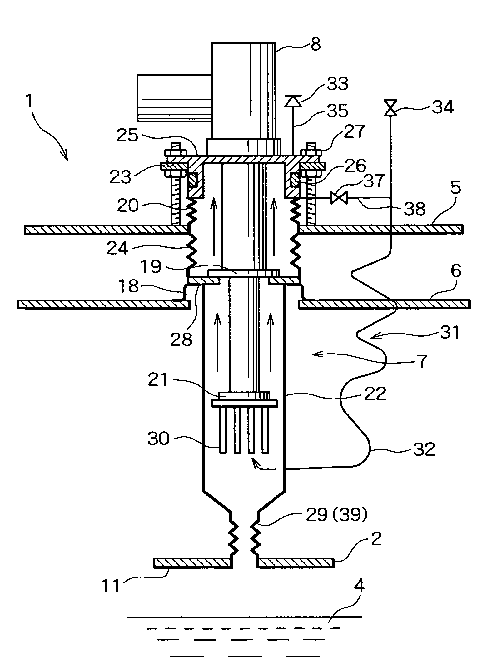
[0054]A tubular refrigerator sleeve 7 extends through the vacuum vessel 5 and the thermal shield 6. A base section of the refrigerator sleeve 7 is communicatively connected into the containment vessel 2 and an opening section of the refrigerator sleeve 7 is opening to the outside of the vacuum...

second embodiment

[0095]A cryogenic system according to the present invention will now be described.

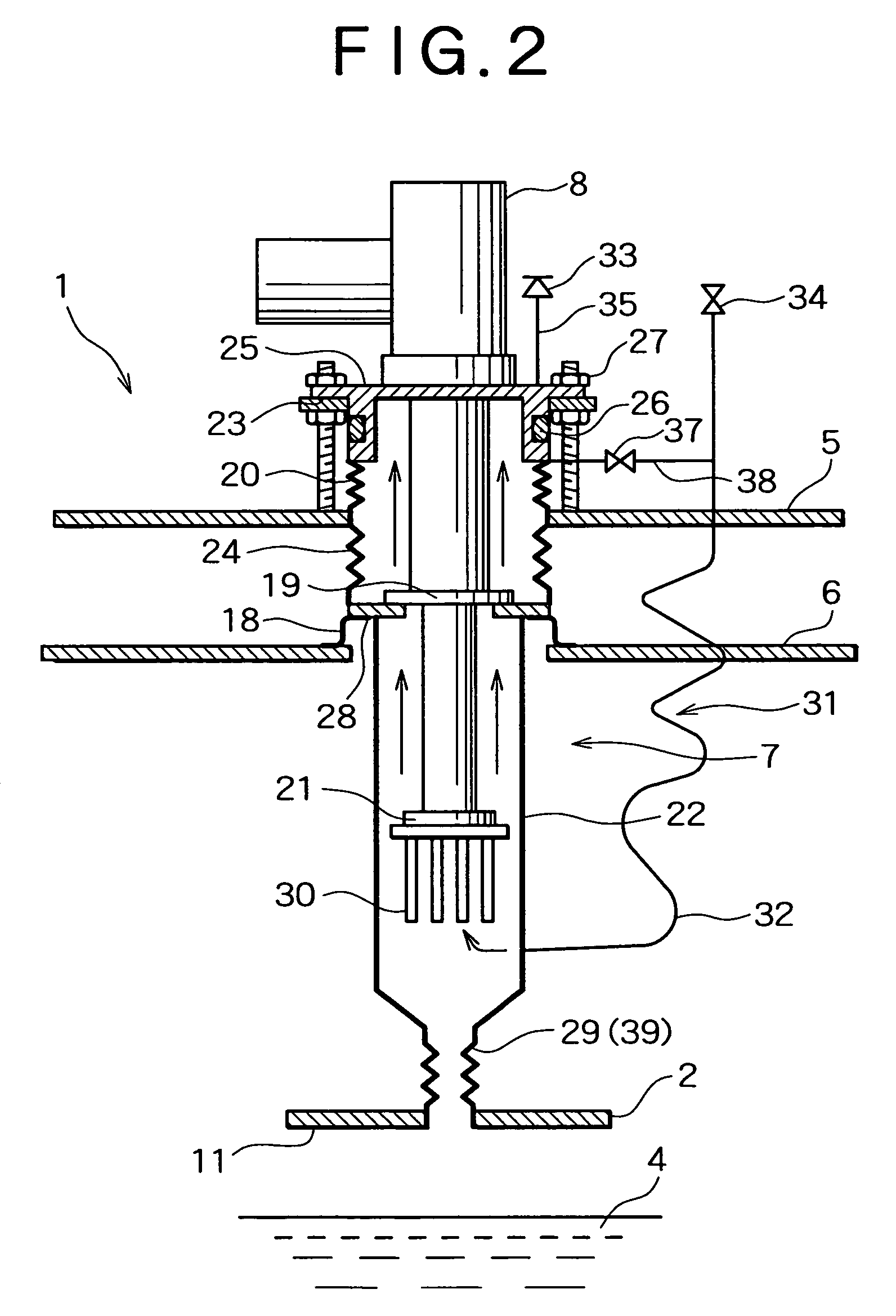
[0096]As shown in FIGS. 4 and 5, in the second embodiment, a gas-blocking means 39 is significantly different from that of the first embodiment; however, other components are substantially the same as those of the first embodiment.

[0097]That is, the gas-blocking means 39 includes a valve body 40 with which a base section of a refrigerator sleeve 7 can be blocked and which can be freely operated from outside.

[0098]That is, the valve body 40 is a copper disk which is provided in a connecting chamber 36 connected to a containment vessel 2 and which is placed below a connecting pipe 29. The valve body 40 includes a disk section 42, placed horizontally, for blocking an aperture section 41 placed between the connecting pipe 29 and the connecting chamber 36; a peripheral section 43 provided such that it perpendicularly extends downward from the edge of the disk section 42; and a flange section 44 extending ou...

third embodiment

[0105]A cryogenic system according to the present invention will now be described.

[0106]As shown in FIG. 6, in the third embodiment, a gas-blocking means 39 is significantly different from that of the second embodiment; however, other components are substantially the same as those of the second embodiment.

[0107]A valve body 40 does not have a disk shape but has a cone shape and an aperture section 41 has a funnel shape (such a shape as an ordinary funnel is upside down) such that a cone section 60 of the valve body 40 is fitted in the aperture section 41. The cone section 60 has a face in contact with the aperture section 41 and a plating layer 50, including two sub-layers, similar to that of the second embodiment is formed on this face.

[0108]Since the valve body 40 has such a cone shape as described above, the valve body 40 has a large area in contact with the aperture section 41; hence, the aperture section 41 can be securely sealed with the valve body 40.


PUM

PropertyMeasurementUnit
cryogenic temperatureaaaaaaaaaa
temperatureaaaaaaaaaa

Abstract

A cryogenic system includes a containment vessel in which a body to be cooled is housed in such a manner that the body is immersed in a liquid coolant; a tubular refrigerator sleeve; and a refrigerator, inserted in the opening section of the refrigerator sleeve, for recondensing coolant gas generated from the coolant, wherein a gas flow-forming means for forming a flow of purge gas toward an opening section of the refrigerator sleeve is provided. The purge gas prevents air from entering a refrigerator sleeve during the replacement of a refrigerator of a cryogenic system.

Description

BACKGROUND OF THE INVENTION[0001]1. Field of the Invention[0002]The present invention relates to a cryogenic system for cooling a superconducting magnet or the like.[0003]2. Description of the Related Art[0004]In conventional apparatuses including superconducting magnets, in order to retain their superconducting properties, it has been necessary to maintain the magnets at a cryogenic temperature close to absolute zero. Examples of a technique for maintaining a magnet at a cryogenic temperature include a technique in which a superconducting magnet is immersed in a coolant such as liquid helium and a technique for directly cooling a superconducting magnet using a cryogenic refrigerator.[0005]FIG. 8 shows a configuration of a known cryogenic system 101. This figure shows a cross section of an MRI system (a magnetic resonance imaging scanner) known as a medical instrument. This system includes a solenoidal superconducting magnet 103 of which the central axis extends horizontally.[0006]T...

Claims


Application Information

Patent Timeline
Patent Type & Authority Patents(United States)
IPC IPC(8): F25B19/00F25B9/00F25B9/14F17C1/00F25D19/00H01F6/00H01F6/04H01L39/04
CPCF17C1/00F17C2270/0536F25D19/006H01F6/04Y02E60/321F17C2201/0104F17C2201/0138F17C2201/0195F17C2203/032F17C2203/0391F17C2205/0329F17C2205/0335F17C2205/0352F17C2221/012F17C2221/017F17C2223/0161F17C2223/033F17C2227/0397F17C2227/044F17C2250/0439F17C2260/042F17C2270/0168F17C2270/0184F25B2400/17Y02E60/32
Inventor MIKI, TAKASHI
Owner KOBE STEEL LTD
Why Eureka
Try Eureka