Vibration generator

Active Publication Date: 2009-10-01
ABI ANLAGENTECHN BAUMASCHEN INDBEBEDARF
View PDF7 Cites 11 Cited by
  • Summary
  • Abstract
  • Description
  • Claims
  • Application Information

AI Technical Summary

Benefits of technology

[0012]In a further development of the invention, the direction of the effect of the vibration generator can be adjusted. In this way, adaptation of the vibration generator to different process requirements, such as pile-driving and retraction, is made possible.
[0013]The means for adjustment of the effect direction can comprise a swivel motor by way of which the phase position, relative to one another, of at least two imbalance groups that rotate at different speeds of rotation can be changed. In this way, a change in the effect direction is made possible, without any conversion measures being required.
[0014]In a further embodiment of the invention,

Problems solved by technology

Because of this periodic uncoupling of ground and goods to be dr

Method used


Image

  • Vibration generator
  • Vibration generator
  • Vibration generator

Examples


Embodiment Construction

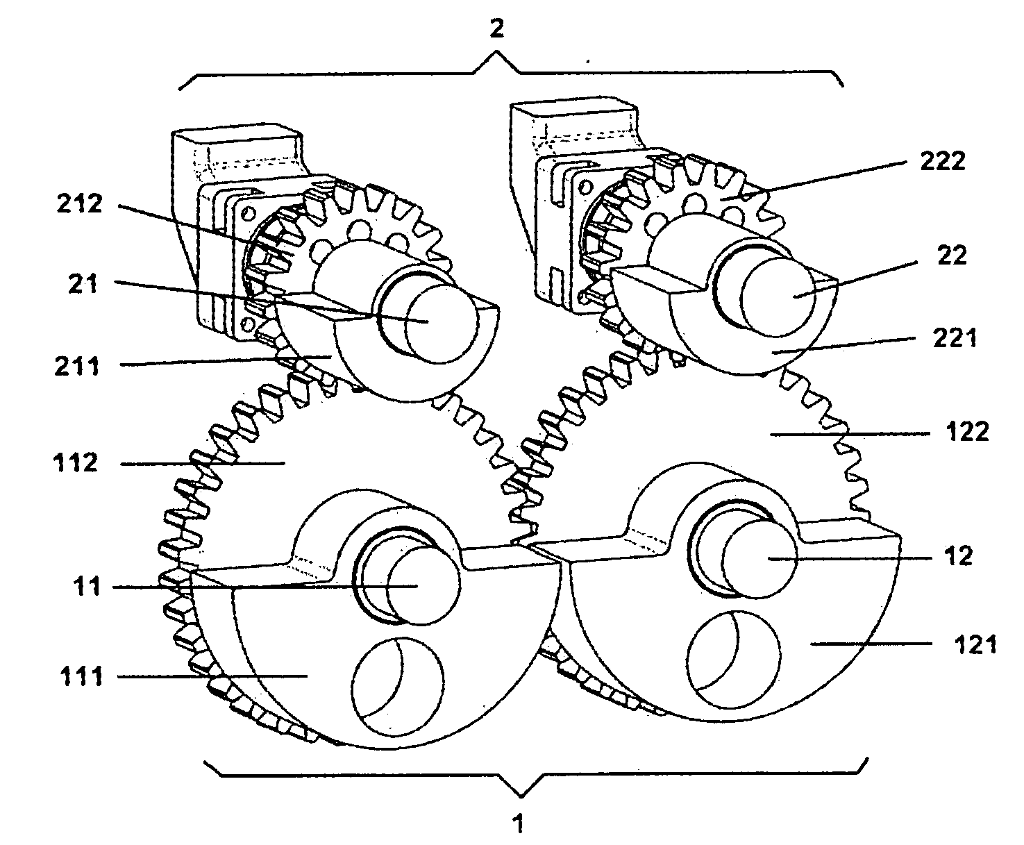
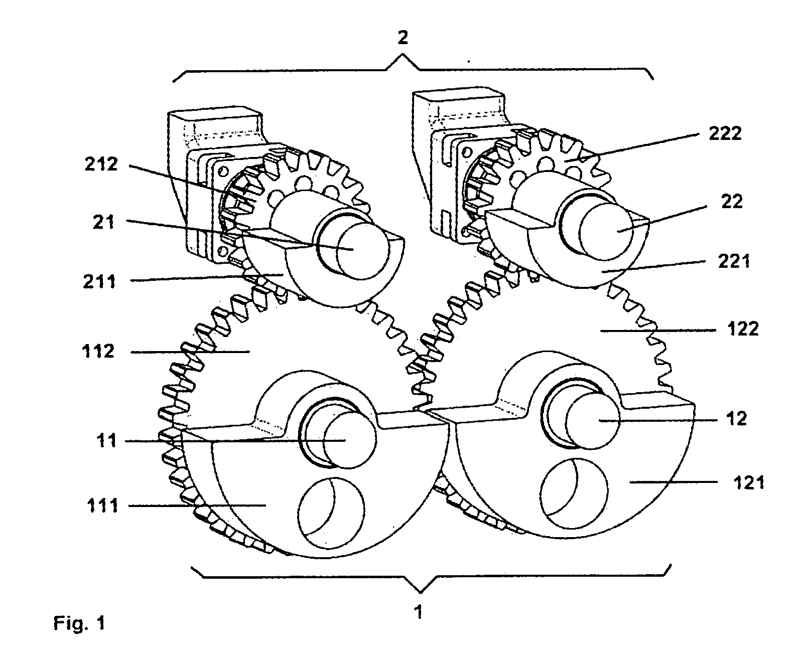
[0030]Referring now in detail to the drawings, the vibration generators selected as exemplary embodiments are configured as vibrator gear mechanisms. Such vibrators consist essentially of a housing, in which shafts provided with gear wheels are mounted. The gear wheels are each provided with imbalance masses. Such vibrator gear mechanisms having imbalance masses mounted to rotate are known to a person skilled in the art, for example from DE 20 2007 005 283 U1. The following explanation of the exemplary embodiments is essentially limited to the arrangement of shafts and imbalance masses.

[0031]In the embodiment according to FIG. 1, two shaft groups 1, 2 are disposed. Shafts 11, 12 of shaft group 1 are provided with gear wheels 112, 122, on which imbalance masses 111, 121, are disposed. Imbalance masses 111, 121 are configured in the same manner in the exemplary embodiment. Shafts 21, 22 of shaft group 2 are also provided with gear wheels 212, 222, on which imbalance masses 211, 221 of...


PUM


Abstract

A vibration generator has two groups of shafts, on which at least two groups of imbalances are disposed, and which are connected with at least one drive, by means of which they are put into rotation. The shaft groups are connected with the at least one drive in such a manner that the speed of rotation of one shaft group amounts to half the speed of rotation of the other shaft group, and the ratio of the static moments of the shaft groups provided with the imbalance groups amounts to between six to one and ten to one.

Description

CROSS REFERENCE TO RELATED APPLICATIONS[0001]Applicants claim priority under 35 U.S.C. §119 of European Application No. 08103162.7 filed Mar. 28, 2008.BACKGROUND OF THE INVENTION[0002]1. Field of the Invention[0003]The invention relates to a vibration generator comprising two, three, or four groups of shafts, on which at least two groups of imbalances are disposed. The shafts are connected with at least one drive, which rotates the shafts at different speeds of rotation.[0004]2. The Prior Art[0005]In construction, vibration generators are used to introduce objects, such as profiles, into the ground, or to draw them from the ground, or also to compact ground material. The ground is excited by vibration, and thereby achieves a “pseudo-fluid” state. The goods to be driven in can then be pressed into the construction ground by a static top load. The vibration is characterized by a linear movement and is generated by rotating imbalances that run in opposite directions, in pairs.[0006]Vib...

Claims


Application Information

Patent Timeline
IPC IPC(8): F16H33/20
CPCY10T74/18344B06B1/166
Inventor HEICHEL, CHRISTIANKLEIBL, ALBRECHT
Owner ABI ANLAGENTECHN BAUMASCHEN INDBEBEDARF
Why Eureka
Try Eureka