Pressure sensor and apparatus for sensing pressure and touch screen including the same

a pressure sensor and touch screen technology, applied in the field of film or panel, can solve the problems of difficult to accurately measure the pressure value, the inability to directly measure the pressure, and the inability to measure the pressure directly. to achieve the effect of increasing the direct pressure measurement

Inactive Publication Date: 2013-08-01
ELECTRONICS & TELECOMM RES INST
View PDF9 Cites 7 Cited by
  • Summary
  • Abstract
  • Description
  • Claims
  • Application Information

AI Technical Summary

Benefits of technology

[0004]The present invention has been made in an effort to provide an apparatus that may increase a direct pressure measurement effect by installing a transparent film type pressure sensor in an upper end of a screen and may also measure an accurate location and a corresponding pressure value even though pressure occurs at a plurality of locations simultaneously.

Problems solved by technology

However, in the case of the above method, since the pressure sensor is disposed in the lower end of the touch screen, it is impossible to directly measure the pressure.
When pressure occurs at a plurality of locations simultaneously, it is difficult to accurately measure a corresponding location and pressure value.

Method used


Image

  • Pressure sensor and apparatus for sensing pressure and touch screen including the same
  • Pressure sensor and apparatus for sensing pressure and touch screen including the same
  • Pressure sensor and apparatus for sensing pressure and touch screen including the same

Examples


Embodiment Construction

[0040]Hereinafter, exemplary embodiments of the present invention will be described in detail with reference to the accompanying drawings. First of all, we should note that in giving reference numerals to elements of each drawing, like reference numerals refer to like elements even though like elements are shown in different drawings. In describing the present invention, well-known functions or constructions will not be described in detail since they may unnecessarily obscure the understanding of the present invention. It should be understood that although exemplary embodiment of the present invention are described hereafter, the spirit of the present invention is not limited thereto and may be changed and modified in various ways by those skilled in the art.

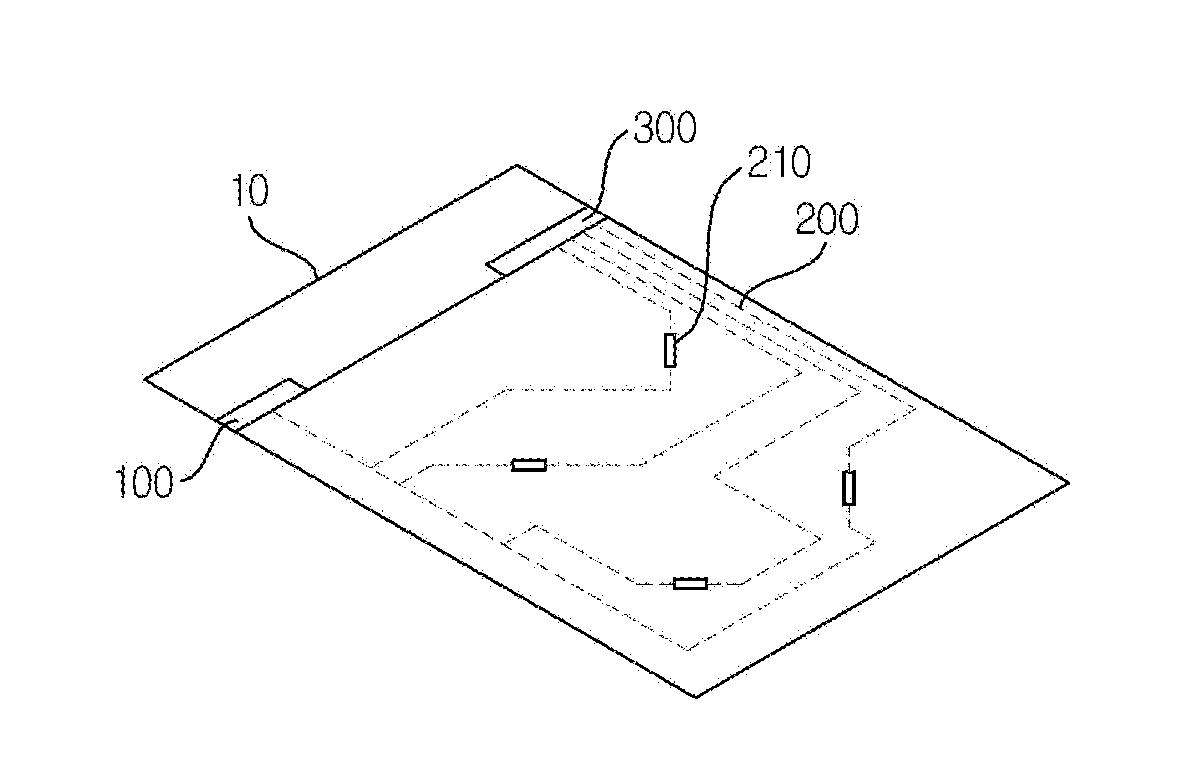
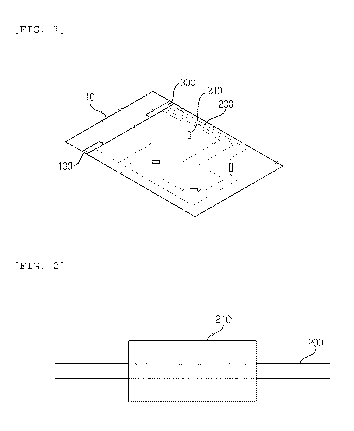
[0041]FIG. 1 is a perspective view illustrating a structure of a pressure sensor 10 according to an exemplary embodiment of the present invention. Referring to FIG. 1, the pressure sensor 10 includes a light source unit 100, an ...


PUM

PropertyMeasurementUnit
pressureaaaaaaaaaa
refractive indexaaaaaaaaaa
areaaaaaaaaaaa

Abstract

Disclosed is a film or a panel that may measure pressure while interacting with an electronic device. A pressure sensor according to the present invention includes: a light source unit to generate light; an optical waveguide to transfer, to a light receiving unit, the light that is generated by the light source unit; and the light receiving unit to receive the light that is transferred through the optical waveguide. The optical waveguide includes a pressure sensing unit to adjust the quantity of light that is transferred through the optical waveguide based on a pressure. The light receiving unit senses the pressure based on the change in the quantity of light that is generated by the light source unit and is transferred through the optical waveguide.

Description

CROSS-REFERENCE TO RELATED APPLICATIONS[0001]This application claims priority to and the benefit of Korean Patent Application No. 10-2012-0007818 filed in the Korean Intellectual Property Office on Jan. 26, 2012, and Korean Patent Application No. 10-2012-0034122 filed in the Korean Intellectual Property Office on Apr. 2, 2012, the entire contents of which are incorporated herein by reference.TECHNICAL FIELD[0002]The present invention relates to a film or a panel that may measure pressure while interacting with an electronic device, and more particularly, to a technology of measuring pressure on a touch screen.BACKGROUND ART[0003]The related art includes a method of measuring pressure by mounting a pressure sensor at a lower end of a touch screen or by employing an external apparatus, and the like. Korea Patent Application No. 2008-0092059 discloses a method of measuring pressure for controlling a touch screen by mounting a pressure sensor in a lower end of the touch screen, or measu...

Claims


Application Information

Patent Timeline
Patent Type & Authority Applications(United States)
IPC IPC(8): G01L1/24G06F3/042
CPCG06F3/0421G01L1/24G06F2203/04109
Inventor KYUNG, KI UKPARK, SUN TAKKIM, YOUNG SUNGPARK, JUN SEOK
Owner ELECTRONICS & TELECOMM RES INST
Why Eureka
Try Eureka