Waste gas heat reclaiming device and stenter setting machine possessing same

A technology of waste gas heat recovery and tenter setting machine, which is applied in indirect heat exchangers, fabric elongation, heat exchanger types, etc. Faster, less hazard, and energy-saving effects

Active Publication Date: 2008-01-09
MONFORTS FONGS TEXTILE MACHINERY ZHONGSHAN
View PDF0 Cites 9 Cited by
  • Summary
  • Abstract
  • Description
  • Claims
  • Application Information

AI Technical Summary

Problems solved by technology

The prior art stenter setting machine adopts the above-mentioned principle, and there are two problems in this stenter setting machine: 1. The temperature of the exhaust gas discharged by the exhaust fan is very high, which not only wastes more heat, but also heats up the environment; 2. Exhaust gas is a kind of mixed gas, which contains some oil gas, wax, water vapor, volatile components, as well as dust, wool, etc., which pollutes the air after being directly discharged into the atmosphere

Method used


Image

  • Waste gas heat reclaiming device and stenter setting machine possessing same
  • Waste gas heat reclaiming device and stenter setting machine possessing same
  • Waste gas heat reclaiming device and stenter setting machine possessing same

Examples


Embodiment Construction

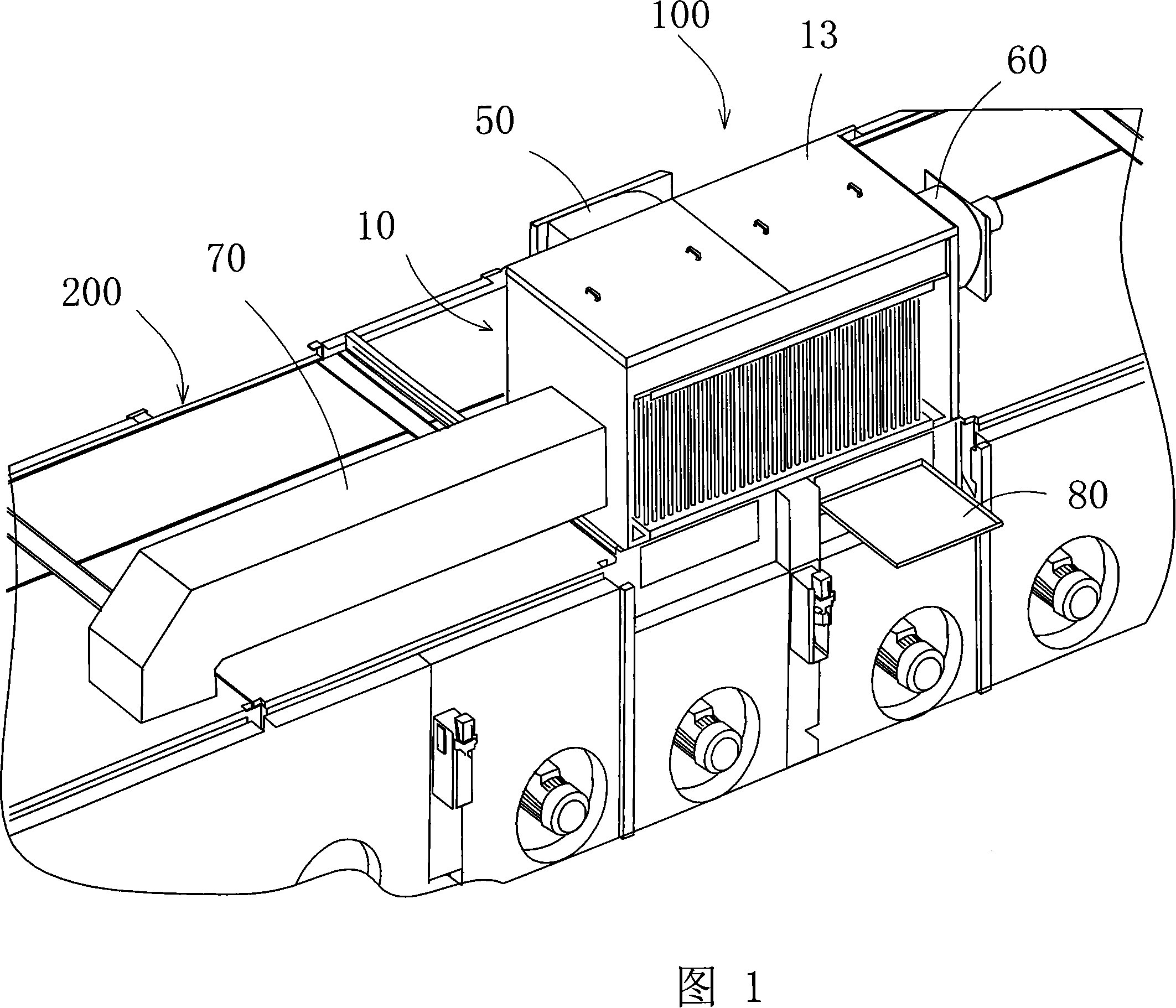
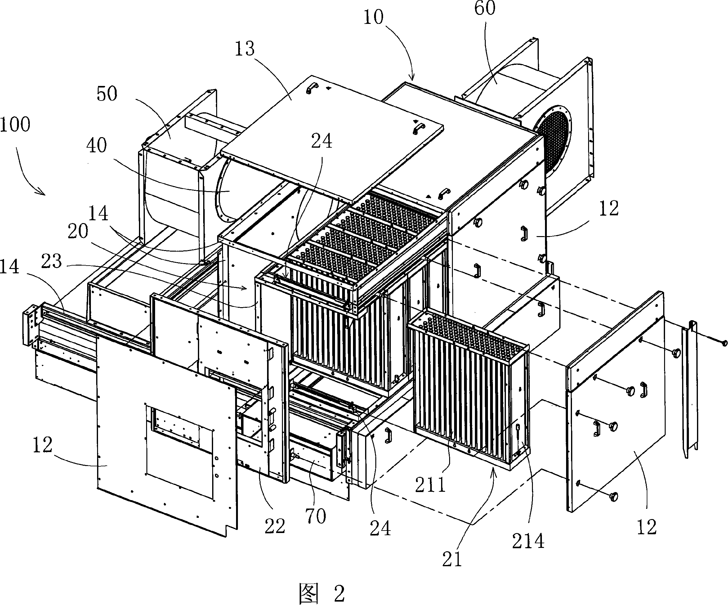
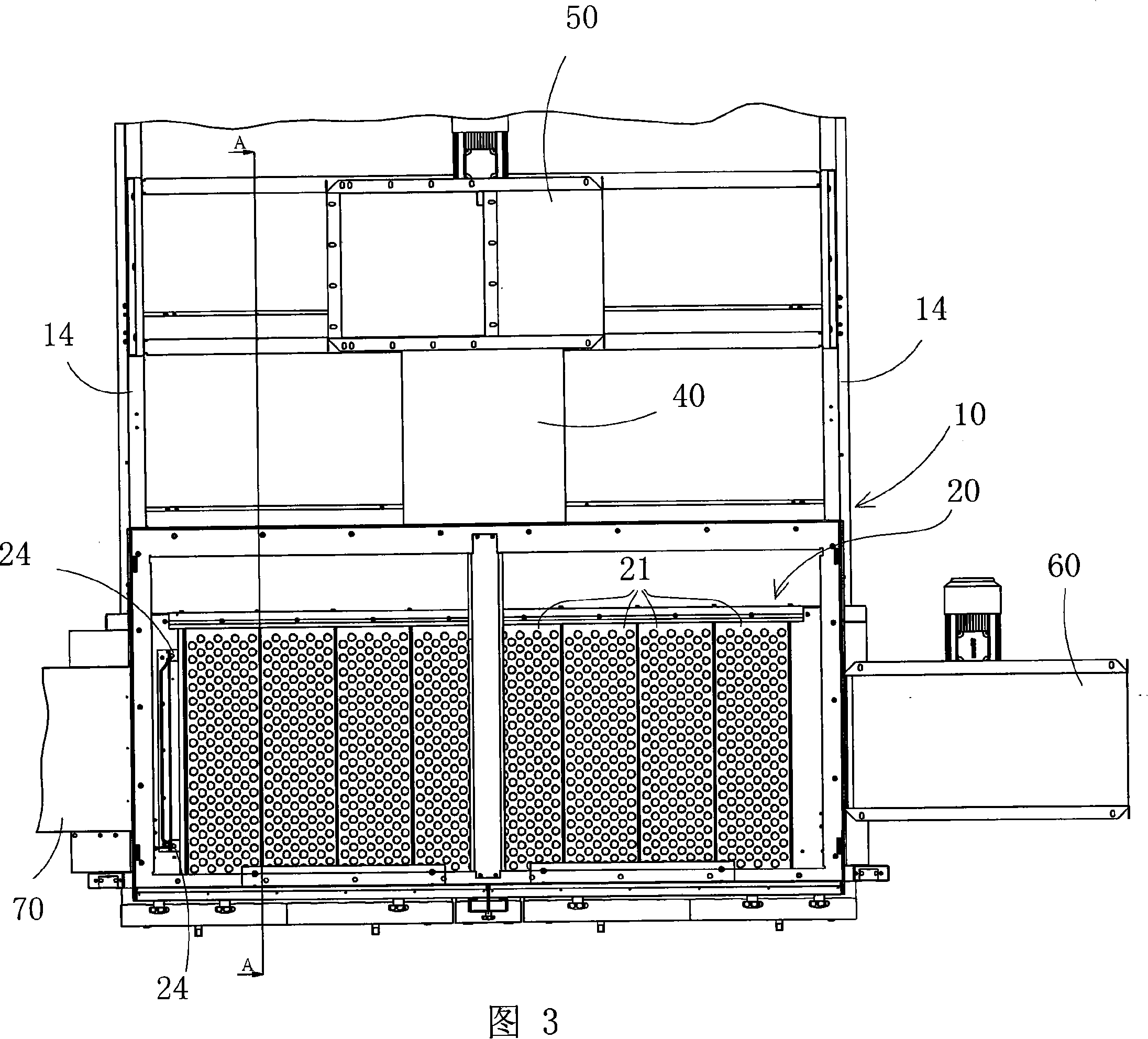
[0028] Referring to Figs. 1 to 4, Fig. 1 is a three-dimensional schematic view of the waste gas heat recovery device of the present invention installed on the top of the oven of the stenter setting machine. In order to facilitate the viewing of the internal heat exchange tube 211, the Front cover plate 12. The waste gas heat recovery device of the present invention has a heat recovery box 10, the heat recovery box 10 is sealed and connected to the box bracket 14 by the surrounding outer sealing plate 12 and the openable upper cover 13, and passes through the box bracket 14 It is formed by sealingly connected to the top of the oven. The rear of the box is connected with an exhaust pipe 40, and the exhaust pipe is connected with an exhaust fan 50. It is through this exhaust fan that the final waste gas is discharged to the outside. The left side of the body is connected with a fresh air blower 60, which sends fresh air into the heat recovery box for heat exchange and obtains hea...


PUM


Abstract

The invention relates to an exhaust heat recovery unit, including the heat recovery box (10), heat exchanger (20) connected to the bottom of the heat recovery box (10), whose upper left the exhaust cavity (11) to accommodate the exhaust gas, in the heat exchange (20) installs a high-temperature exhaust heat exchange channels and fresh air channel, the exhaust of the high temperature exhaust channel after cooling, purification through the exhaust pipe, the exhaust machine to the outside; the air in the fresh air channel after absorbing the heat of the exhaust gas send to the oven of the bottom of the exhaust heat recovery unit by the air corridor (70). The breadth draw setting machine which carries the above exhaust heat recovery unit includes multi-oven (200), in which at least one oven (200) installs the above stated the exhaust heat recovery unit (100). The setting machine and its exhaust heat recovery unit recycle the heat of the exhaust gas which is discharged by the breadth draw setting machine, save energy, clean exhaust and reduce the emissions of temperature, protect the environment.

Description

technical field [0001] The invention relates to textile machinery, in particular to a waste gas heat recovery device of a stenter setting machine, and a stenter setting machine with the waste gas heat recovery device. Background technique [0002] Stenter setting machine is a kind of textile machinery, which is the main equipment used for dehydration, finishing, drying, baking and heat setting of fabrics. The air in the oven is heated by hot oil, hot steam, gas, electricity, etc., and the hot air is drawn out by the circulating fan and sprayed on the surface of the fabric through the upper and lower nozzles. The cooled air is heated again, and so on. The exhaust gas generated in the oven is discharged into the atmosphere through the exhaust fan and the exhaust pipe, and the oven supplements a certain amount of room temperature air through the gaps at both ends to maintain the air pressure balance of the oven. The stenter setting machine of the prior art adopts the above-me...

Claims


Application Information

Patent Timeline
Patent Type & Authority Applications(China)
IPC IPC(8): F28D1/053D06C3/00
Inventor 云维庸
Owner MONFORTS FONGS TEXTILE MACHINERY ZHONGSHAN
Why Eureka
Try Eureka