Sheet stacking apparatus and image forming system using the same

a stacking apparatus and image forming technology, applied in the direction of electrographic process, instruments, transportation and packaging, etc., can solve the problems of reducing the image forming speed of the image forming apparatus, the inability of the sheet stacking apparatus to receive the sheets, and the inability to properly align the sheet alignment operation

Active Publication Date: 2009-10-01
KONICA MINOLTA BUSINESS TECH INC
View PDF5 Cites 26 Cited by
  • Summary
  • Abstract
  • Description
  • Claims
  • Application Information

AI Technical Summary

Problems solved by technology

However, if the shifting operation of the aligning plate is not completed, the aligning operation of the sheets cannot be properly conducted, and sometimes the sheet aligning plate interferes in ejecting the sheets.
However, in the above described technology, in which the sheet conveyance speed is lowered, and the sheet conveyance interval is increased, when plural greater conveyance intervals are to be provided (that is, when the number of sheets to be sorted as a single unit is relatively small, and said units are in the series), the conveyance route of the sheet stacking apparatus becomes full with sheets, so that the sheet stacking apparatus cannot receive the sheets which are ejected from the image forming apparatus.
Accordingly, depending on circumstances, the image forming speed of the image forming apparatus needs to be lowered, which is a problem from the point of view of the productivity conducted by the image forming apparatus.
However, if the number of sheets to be sorted as a unit is only one, said sheet is included within another unit, that is, said sheet cannot be temporarily stacked alone.
Accordingly, in the above technology, the image forming speed of the image forming apparatus must be lowered, which is also a problem from the point of view of the productivity conducted by the image forming apparatus.

Method used


Image

  • Sheet stacking apparatus and image forming system using the same
  • Sheet stacking apparatus and image forming system using the same
  • Sheet stacking apparatus and image forming system using the same

Examples


Embodiment Construction

Brief Description of the Image Forming System

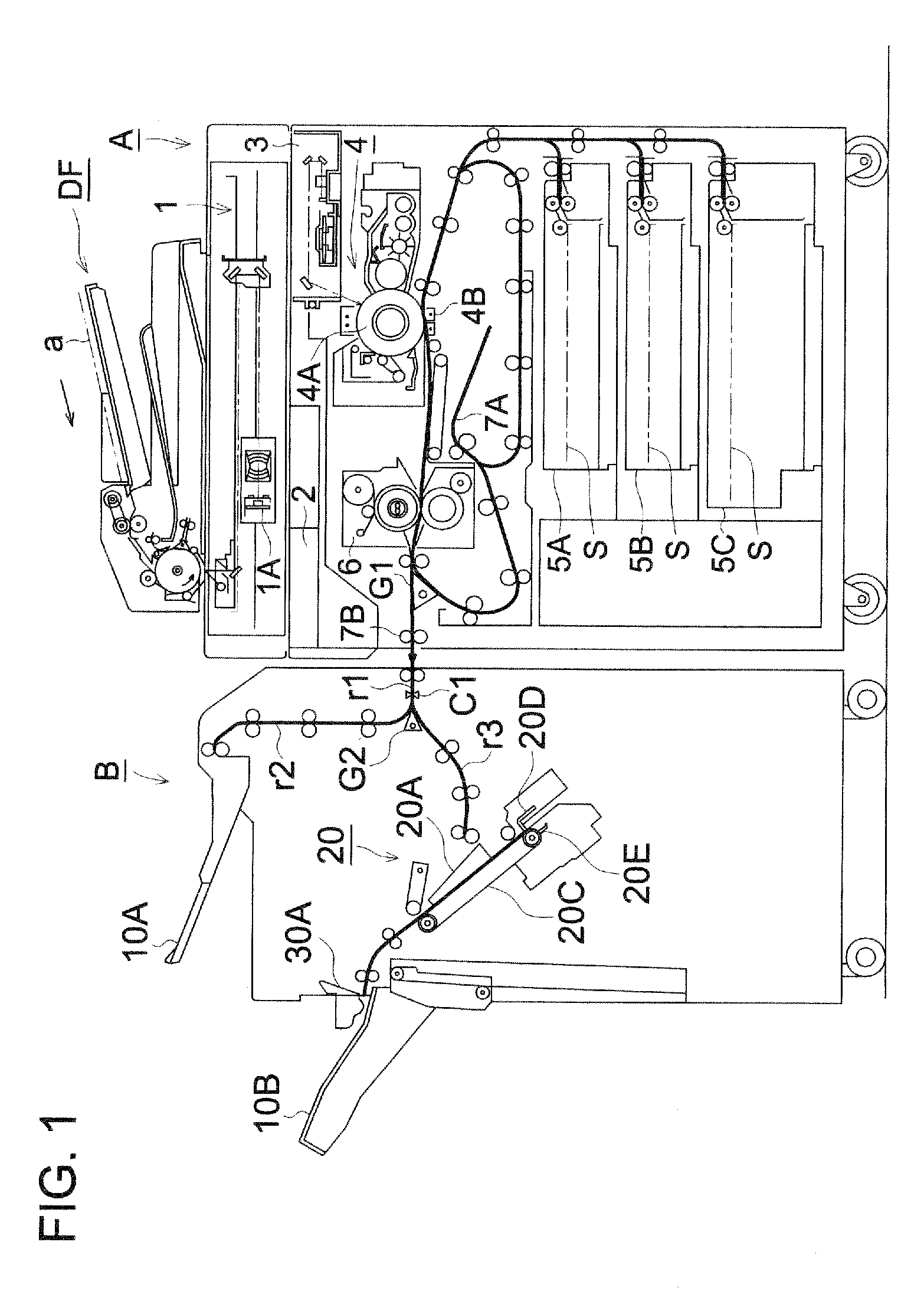
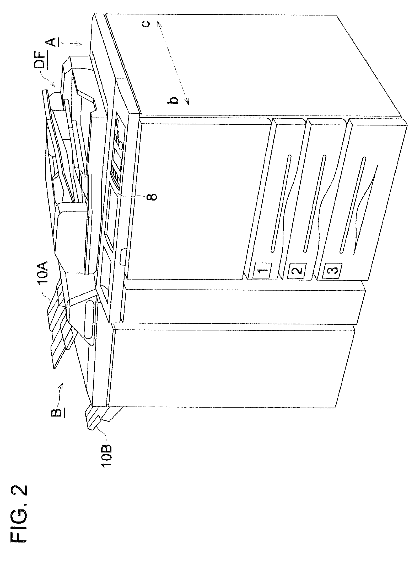
[0032]FIG. 1 shows the total structure of the image forming system, which includes image forming apparatus A, automatic document feeding device DF, and sheet stacking apparatus B.

[0033]Image forming apparatus A shown in FIG. 1 includes image reading section 1, image processing section 2, image writing section 3, and image forming section 4. Automatic document feeding device DF is mounted on a top portion of image forming apparatus A, and sheet stacking apparatus B is combined to the left side of image forming apparatus A.

[0034]Document “a”, placed on a document reading plate of automatic document reading device DF, is fed in the arrowed direction, whereby, images, carried on a single surface or both surfaces of document “a”, are read by image sensor 1A of image reading section 1. Analog signals, photo-electrically converted by image sensor 1A, are processed by image processing section 2, with respect to analog processing, A / D conversion, ...


PUM

PropertyMeasurementUnit
timeaaaaaaaaaa
image forming speedaaaaaaaaaa
sheet conveyance speedaaaaaaaaaa

Abstract

A sheet stacking apparatus including a stacking section which stacks sheets; a sorting section which changes an ejecting position of the sheet in the stacking device to sort the sheets; an aligning section which aligns the sheet sorted by the sorting section and ejected onto the stacking section; a shifting section which shifts the aligning section based on the ejecting position changed by the sorting section in the stacking section; and a control section which controls at least the aligning section and the shifting section; wherein when the number of sheets as a sheet unit to be sorted by the sorting section is plural, the control section controls the aligning section to align the sheets as the sheet unit, and when the number of sheets is singular, the control section controls at least the aligning section and shifting section not to align the single sheet in the sheet unit.

Description

CROSS REFERENCE TO RELATED APPLICATION[0001]This application is based on Japanese Patent Application No. 2008-083127 filed on Mar. 27, 2008, with the Japanese Patent Office, the entire content of which is hereby incorporated by reference.TECHNICAL FIELD[0002]The present invention relates to a sheet stacking apparatus including a sheet sorting function and a sheet aligning function, and an image forming system including said sheet stacking apparatus.BACKGROUND OF THE INVENTION[0003]Concerning the sheet stacking apparatus, which is combined with the image forming apparatus, such as a copy machine or a printer, to eject a large number of sheets, many said devices have the sheet sorting function to change a sheet ejecting position for sorting such sheets. Further, many said devices have the sheet aligning function to align the plural sorted sheets.[0004]The sheet stacking apparatuses, including the sheet sorting function and the sheet aligning function, are configured to sort the sheets...

Claims


Application Information

Patent Timeline
Patent Type & Authority Applications(United States)
IPC IPC(8): B65H31/00
CPCB65H31/10B65H31/34B65H2513/51G03G2215/00902G03G15/6547B65H2301/4212B65H2301/42192B65H2404/725B65H2404/742B65H2511/10B65H2801/06B65H2220/01B65H2220/02
Inventor KONISHI, HIROYUKI
Owner KONICA MINOLTA BUSINESS TECH INC
Why Eureka
Try Eureka