
Wheel weight

a technology of wheel and weight, which is applied in the field of wheel weights, can solve the problems of waste of adhesive weight segments, difficulty for the user of the adhesive weight, and the shape of traditional adhesive weights, and achieve the effects of convenient separation, convenient installation, and rigidity

Inactive Publication Date: 2009-10-01
HENNESSY IND
View PDF45 Cites 27 Cited by
  • Summary
  • Abstract
  • Description
  • Claims
  • Application Information

AI Technical Summary

Benefits of technology

The present invention provides various configurations of vehicle wheel weights that can be attached to a curved surface of a wheel rim. The weights can be made of iron or low carbon steel, and may include a top lip portion and a bottom lip portion that extend outwardly from the weight segments. The weights can be adhesively secured to the rim using adhesive tape, and may have a removable tape liner for easy removal. The weights can be easily installed and removed, and may be attached to the wheel rim without the use of a separate tool. The technical effects of the invention include improved weight distribution, reduced weight, and increased flexibility and ease of installation.

Problems solved by technology

The shape of the traditional adhesive weights may not be advantageous for placing the weight on a curved surface, such as the inner periphery of the wheel's rim.
In some circumstances, it can be difficult for the user of the adhesive weight to remove the tape liner from the tape.
Also, the tape liner may be inadvertently removed from too many weight segments, thus creating adhesive weight segments that are wasted.
This step adds time and expense to the wheel weight application process.

Method used


Image

  • Wheel weight
  • Wheel weight
  • Wheel weight

Examples


Embodiment Construction

[0032]Reference will now be made in detail to presently preferred embodiments of the invention, one or more examples of which are illustrated in the accompanying drawings. Each example is provided by way of explanation, not limitation, of the invention. In fact, it will be apparent to those skilled in the art that modifications and variations can be made in the present invention without departing from the scope and spirit thereof. For instance, features illustrated or described as part of one embodiment may be used on another embodiment to yield a still further embodiment. Thus, it is intended that the present invention covers such modifications and variations as come within the scope of the appended claims and their equivalents.

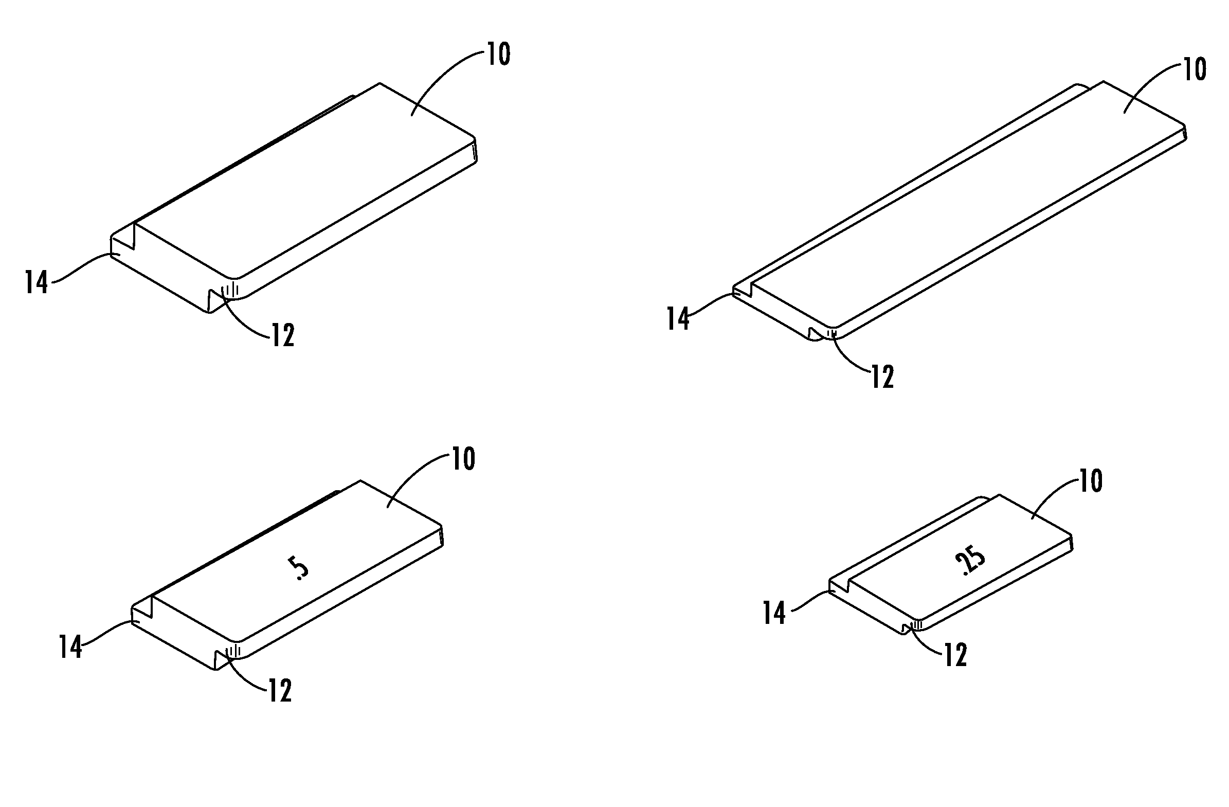
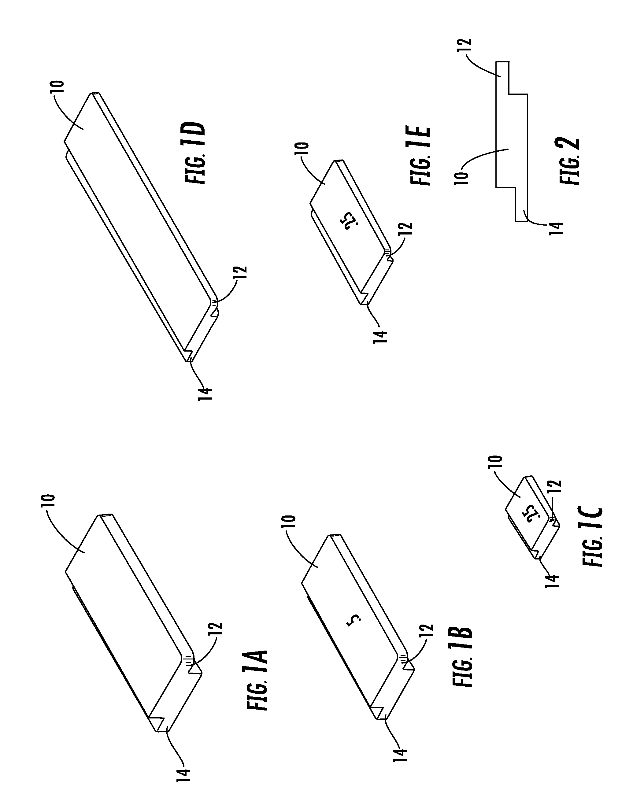
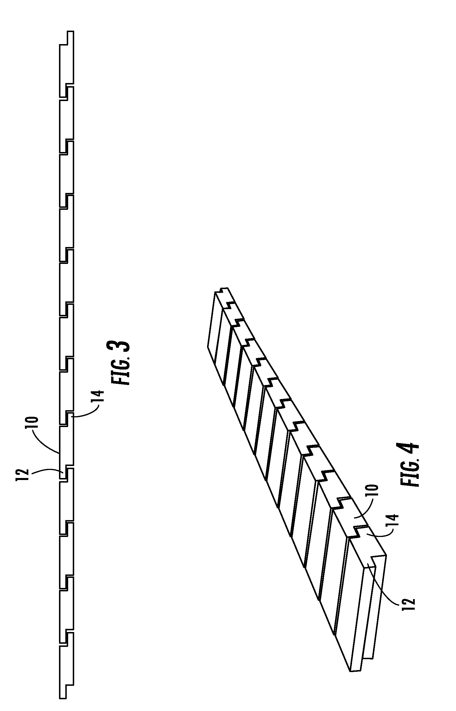
[0033]FIGS. 1A through 1E illustrate a vehicle wheel weight segment 10 constructed in accordance with a first embodiment of the present invention. As shown, wheel weight segment 10 preferably includes a top lip portion 12 and a bottom lip portion 14. In pref...


PUM

PropertyMeasurementUnit
massaaaaaaaaaa
massaaaaaaaaaa
weightaaaaaaaaaa

Abstract

A wheel weight segment for use on a wheel including a rim, having a body with a top surface, a bottom surface, a first side and a second side disposed opposite the first side. A top lip portion with a top surface extends outwardly from the first side of the body and a bottom lip portion with a bottom surface extends outwardly from the second side of the body. The top surface of the body and the top surface of the top lip portion lie in a first plane, and the bottom surface of the body and the bottom surface of the bottom lip portion lie in a second plane.

Description

CLAIM OF PRIORITY [0001]This application claims priority to U.S. Provisional Patent Application Ser. Nos. 61 / 041,056 filed Mar. 31, 2008, and 61 / 041,807 filed Apr. 2, 2008, the entire disclosures of which are hereby incorporated by reference.FIELD OF THE INVENTION [0002]The present invention generally relates to wheel weights. More particularly, the invention relates to adhesive wheel weights placed on the rim of a wheel.BACKGROUND OF THE INVENTION [0003]In order to reduce excessive vibration, vehicle wheels are often balanced by placing weights at selected locations. The weights typically include a mass portion which is attached to a rim of the wheel using a spring clip or a suitable adhesive. Due to high mass and low cost, such weights have been made of lead. Because of various factors, however, it is becoming desirable to manufacture such weights of materials other than lead. The shape of the traditional adhesive weights may not be advantageous for placing the weight on a curved ...

Claims


Application Information

Patent Timeline
Patent Type & Authority Applications(United States)
IPC IPC(8): B60B15/28B23P11/00
CPCY10T29/49822F16F15/328
Inventor PENICHE, ROGERBRANDT, GUIDOKEEFE, KEVIN
Owner HENNESSY IND
Learn More