Waveguide filter

a filter and waveguide technology, applied in the field of waveguide filters, can solve the problems of difficult realization of e-plane discontinuities, heavy weight, and high cost, and achieve the effect of suppressing radiation losses in the siw cavity and high out-of-band rejection

Inactive Publication Date: 2009-10-01
HER MAJESTY THE QUEEN & RIGHT OF CANADA REPRESENTED BY THE MIN OF IND THROUGH THE COMM RES CENT
View PDF7 Cites 125 Cited by
  • Summary
  • Abstract
  • Description
  • Claims
  • Application Information

AI Technical Summary

Benefits of technology

[0009]According to the present invention, a substrate integrated waveguide (SIW) filter includes a chain of sequentially coupled conterminous multimode SIW cavities, of which the first and the last multimode SIW cavities can be directly excited by a transmission line. The entire filter is implemented using arrays of metalized via holes on a dielectric substrate. The via holes are produced by using a standard printed circuit board (PCB) or other planar circuit manufacturing process. The diameter of the via holes and the pitch between neighboring via holes are selected so as to suppress radiation losses in the SIW cavities. A desired passband is generated by the fundamental mode of propagation in the SIW cavitie

Problems solved by technology

These are relatively heavy, bulky, and expensive; due to their size and weight, integration of bulk waveguide filters with planar components and electronic circuits can be a challenging task.
Although various techniques have been implemented to improve the stopband performance of conventional rectangular waveguide filters, these techniques often utilize E-plane discontinuities that are difficult to realize for SIW filters implemented on a single-layer substrate.
The SIW filters of the prior art have often been

Method used


Image

  • Waveguide filter
  • Waveguide filter
  • Waveguide filter

Examples


Embodiment Construction

[0027]While the present teachings are described in conjunction with various embodiments and examples, it is not intended that the present teachings be limited to such embodiments. On the contrary, the present teachings encompass various alternatives, modifications and equivalents, as will be appreciated by those of skill in the art. In FIGS. 6, 7, 8, 9A, and 9B, like numerals refer to like elements.

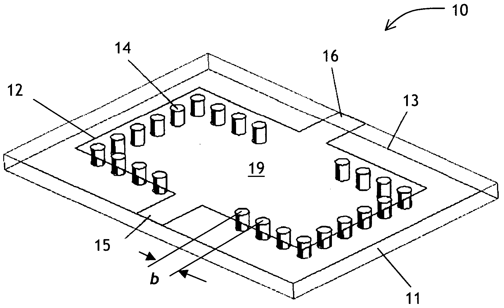
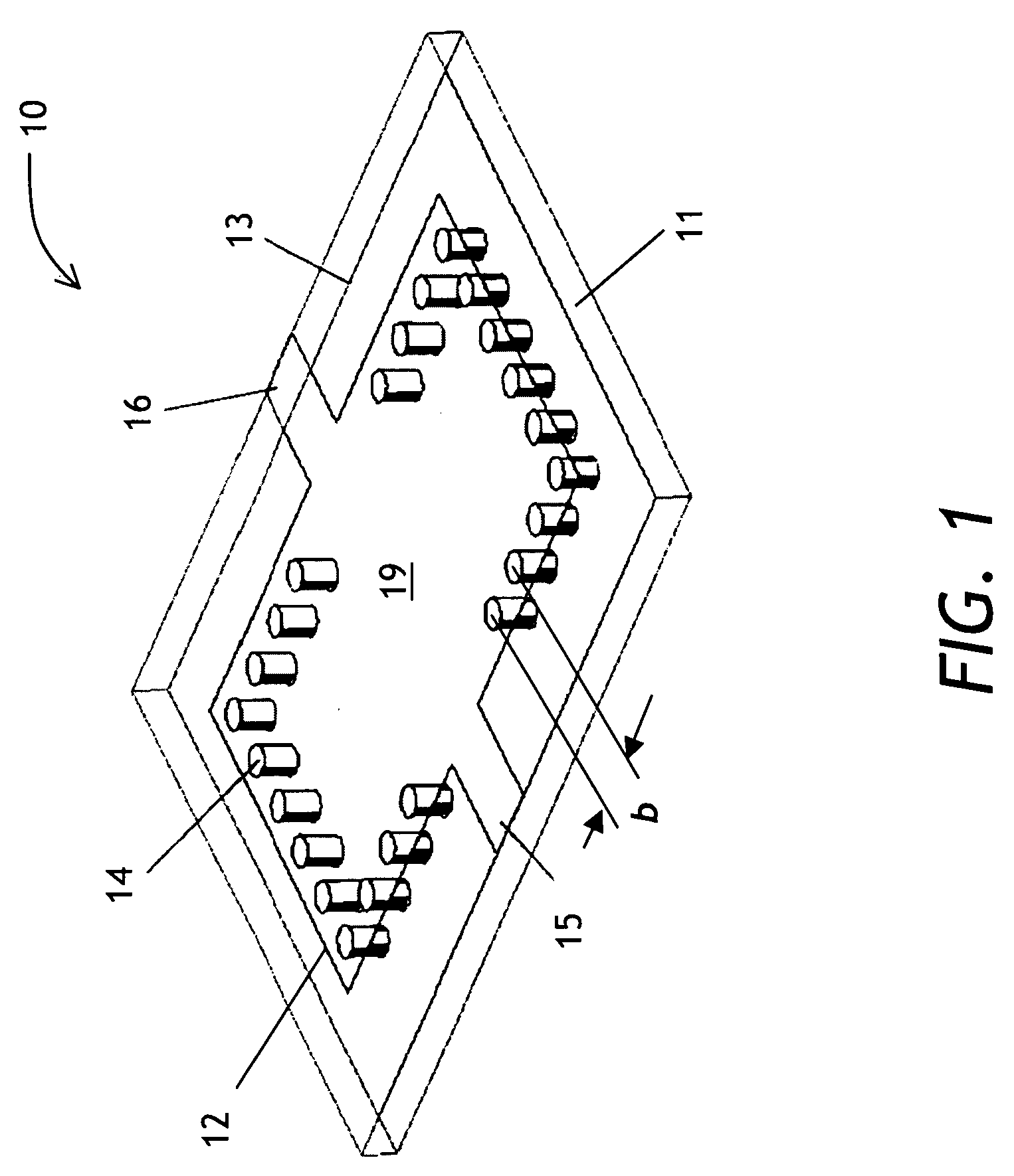
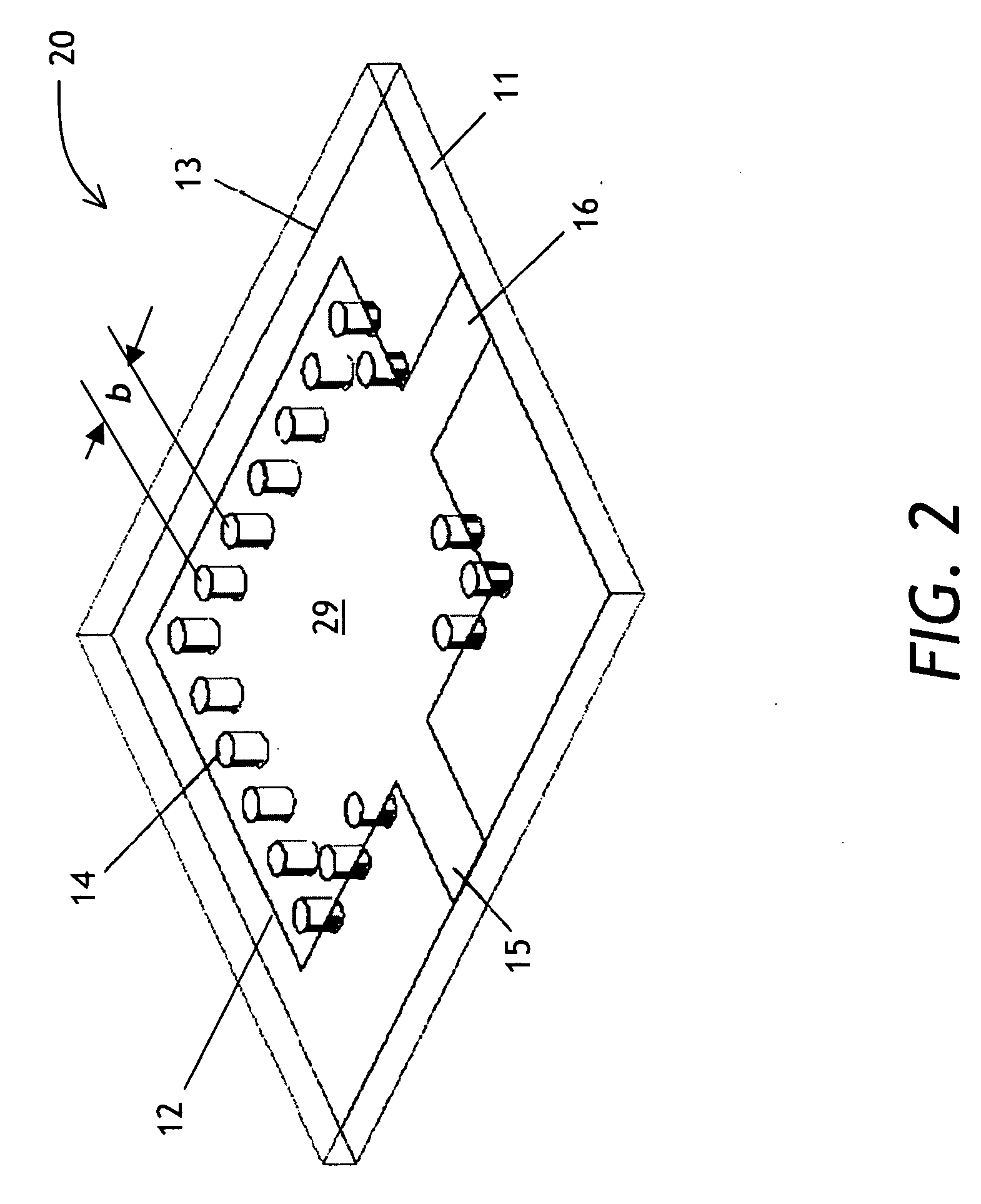
[0028]A waveguide filter of the present invention uses at least two electromagnetic modes, propagating or evanescent. A passband of the filter is defined by a frequency range at which only the fundamental mode appears at an output port of the filter. A stopband of the filter is defined by all frequencies outside of the passband. Within the stopband, higher-order modes may create spurious passbands. By carefully selecting the dimensions of the substrate integrated waveguide (SIW) cavity, one transmission zero (TZ) or multiple TZs can be generated at specific locations in the stopband to su...


PUM


Abstract

A waveguide bandpass filter for use in microwave and millimeter-wave satellite communications equipment is presented. The filter is based on a substrate integrated waveguide (SIW) having several cascaded oversized SIW cavities. The filter is implemented in a printed circuit board (PCB) or a ceramic substrate using arrays of standard metalized via holes to define the perimeters of the SIW cavities. Transmission lines of a microstrip line, a stripline or coplanar waveguide are used as input and output feeds. The transmission lines have coupling slots for improved stopband performance. The filter can be easily integrated with planar circuits for microwave and millimeter wave applications.

Description

CROSS-REFERENCE TO RELATED APPLICATIONS[0001]The present invention claims priority from U.S. Provisional Patent Application No. 61 / 039,942, filed Mar. 27, 2008, and Canadian Patent Application No. 2,629,035, filed Apr. 11, 2008, which are incorporated herein by reference.TECHNICAL FIELD[0002]This invention relates to waveguide filters. More particularly, this invention relates to substrate integrated waveguide bandpass filters.BACKGROUND OF THE INVENTION[0003]An electrical bandpass filter is a fundamental element used for selecting an electrical signal in a frequency passband while suppressing electrical signals in a frequency stopband of the filter. Microwave and millimeter-wave bandpass filters are often used in modern radio-frequency transceivers. Filters having low in-band insertion loss, high spectral selectivity, and a wide stopband are commonly required. As an example, in a typical ground terminal for communication with satellites in the Ka frequency band, a filter is require...

Claims


Application Information

Patent Timeline
IPC IPC(8): H01P1/20
CPCH01P1/2088
Inventor CHEN, XIAO-PINGWU, KEDROLET, DAN
Owner HER MAJESTY THE QUEEN & RIGHT OF CANADA REPRESENTED BY THE MIN OF IND THROUGH THE COMM RES CENT
Why Eureka
Try Eureka