
Driving method, compensation processor and driver device for liquid crystal display

a liquid crystal display and driver device technology, applied in the direction of instruments, static indicating devices, etc., can solve problems such as degrading the display effect of lcd

Inactive Publication Date: 2009-10-01
BEIJING BOE OPTOELECTRONCIS TECH CO LTD
View PDF4 Cites 24 Cited by
  • Summary
  • Abstract
  • Description
  • Claims
  • Application Information

AI Technical Summary

Benefits of technology

[0008]An object of the invention is to provide a driving method, compensation processor and driver device for LCD, for eliminating the flicking occurring on the LCD.
[0020]As can be seen from above solutions, the invention employs the technical means of generating a plurality of back light driver pulse signals, realizes the gradual changing of the brightness of the back lights, thus overcomes the picture flickering problem due to the sudden changing of the brightness of the back lights. Therefore, the solution of the invention can improve the display effect of the LCD and increase the dynamic contrast of the image display.

Problems solved by technology

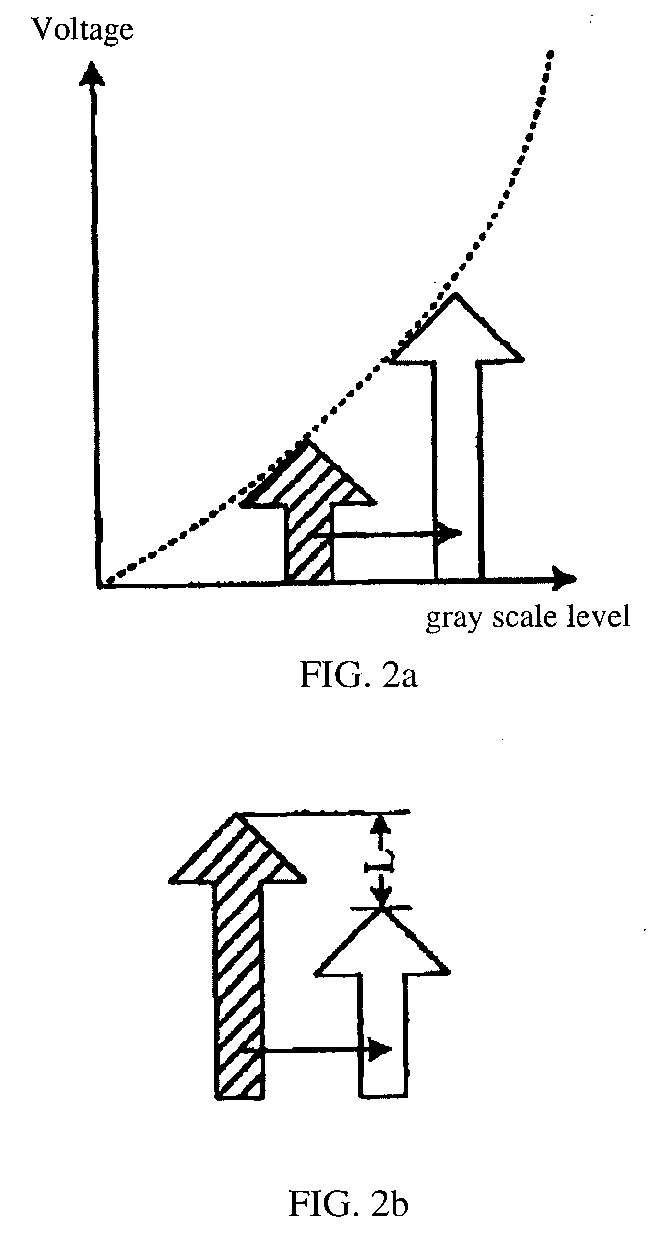
However, the prior LCD employing the driving method by using the Dynamic Contrast technology has the disadvantage in that: although the data signal may be compensated for by analyzing the spectrum of the data signal, thus changing the output data signal according to the set driving frequency, because the change of the brightness of the back lights has the stepwise characteristic and is not smooth, a sudden changing of the brightness of the back lights will occur in the picture of neighboring frames after said compensation and adjustment, which may cause the appearance of flicking, and thus degrading the display effect of the LCD.

Method used


Image

  • Driving method, compensation processor and driver device for liquid crystal display
  • Driving method, compensation processor and driver device for liquid crystal display
  • Driving method, compensation processor and driver device for liquid crystal display

Examples


Embodiment Construction

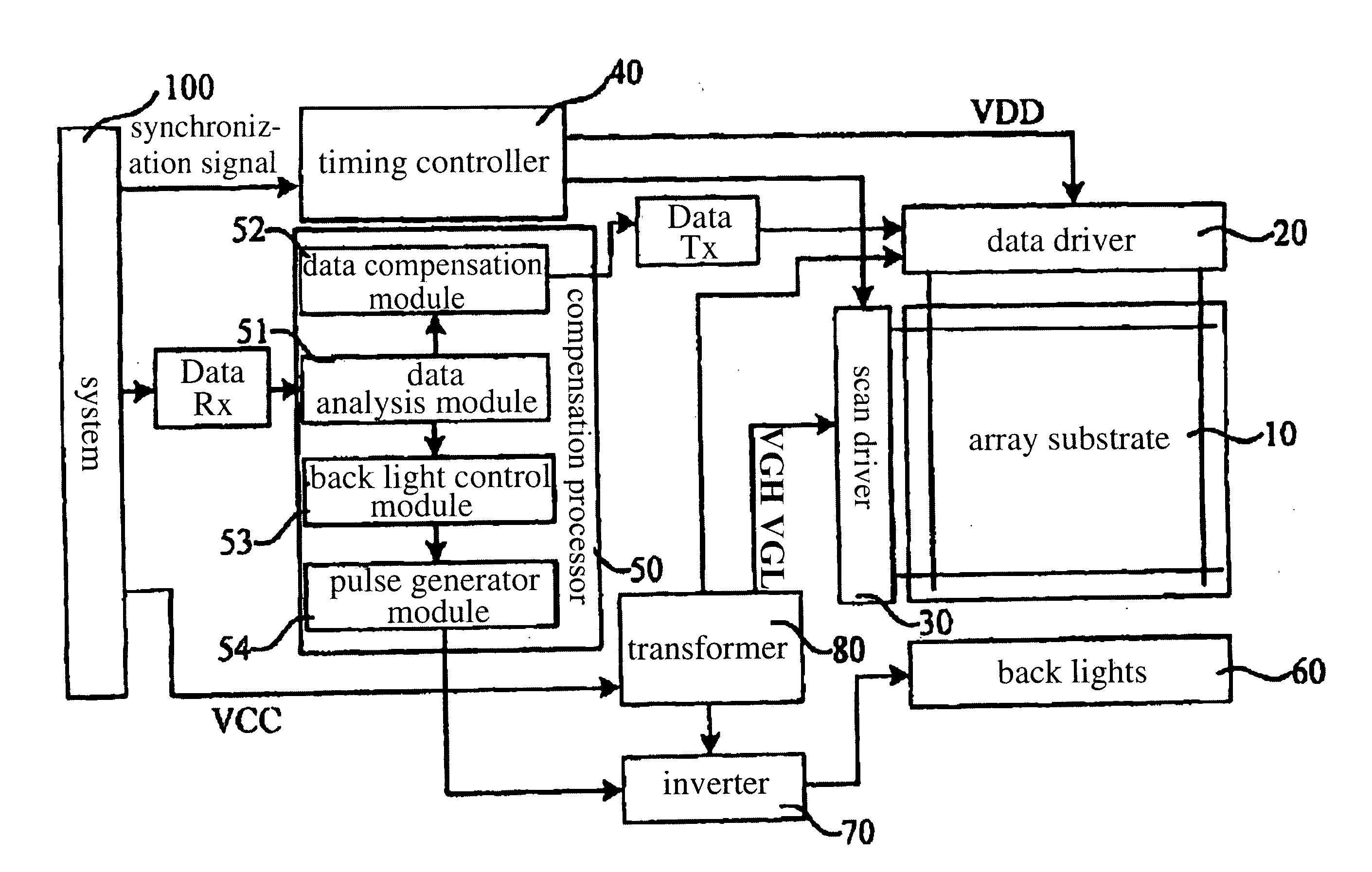
[0051]FIG. 4 is a flow chart of an embodiment of the driving method for LCD of the present invention, the driving method is adapted to realize the driving of the back lights in the procedure of the LCD driving, the steps are:

[0052]Step A1: the compensation processor receives three primary colors (R, G, B) data signal from the system, while the timing controller receives the synchronous signal from the system, and the transformer receives a power voltage from the system;

[0053]Step A2: the compensation makes spectrum analysis on the data signal, obtains an average brightness value of the present frame and records the average brightness value of the present frame;

[0054]Step A3: the compensation processor queries and obtains an average brightness value of the previous frame and the average brightness value of the present frame, and compares the average brightness value of the present frame with the average brightness value of the previous frame;

[0055]Step A4: the compensation processor ...


PUM


Abstract

The invention relates to a driving method, compensation processor and driver device for liquid crystal display. The driving method includes steps of receiving data signal of a present frame; obtaining an average brightness value of the present frame; comparing the previous frame with the present frame, and when the difference between the average brightness values is larger than or equal to a set threshold, generating at least two back light driver pulse signals of which the duty ratios gradually changing, and outputting them to drive the back lights. The compensation processor includes a data analysis module, a data compensation module, a back light linear filtering module and a pulse generator module. The driver device employs the compensation processor of the present invention. The present invention employs the technical means of generating a plurality of back light driver pulse signals, realizes the gradual changing of the brightness of the back lights, and overcomes the picture flickering problem due to the sudden changing of the brightness of the back lights, thus improving the display effect of the LCD.

Description

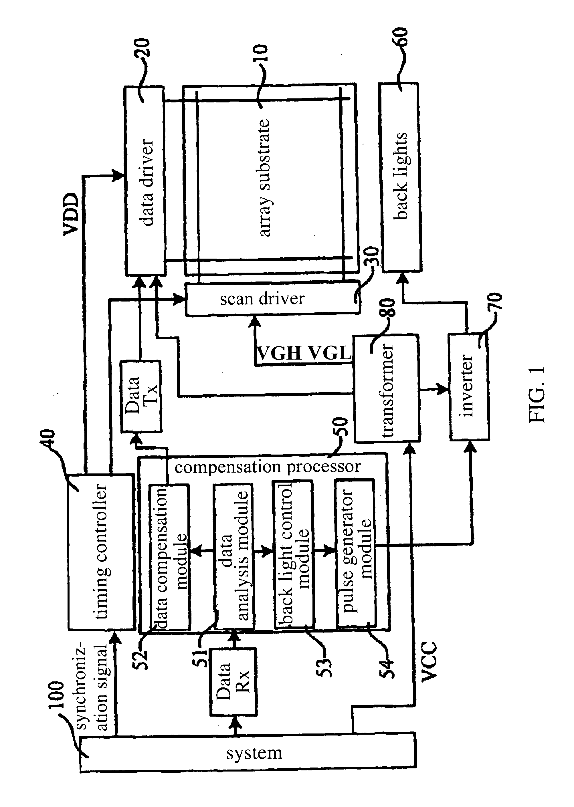
FIELD OF THE INVENTION[0001]This invention relates to a driving method, compensation processor and driver device for liquid crystal display, and particularly to a driving method for analyzing and then compensating video data input to liquid crystal display, a compensation processor for implementing the analysis and compensation, and a driver device utilizing the compensation processor.DESCRIPTION OF THE PRIOR ART[0002]Liquid crystal display, especially the Thin Film Transistor-Liquid Crystal Display (TFT-LCD) has the advantages of low weight, low thickness, low power consumption, suitable for low voltage driving and so on, and is widely used in various image display media apparatus such as mobile phone, monitor, TV, etc.[0003]The main structure of the common LCD at present includes an array substrate and a color film substrate set to box as a liquid crystal panel, and liquid crystal material is filled there-between. A plurality of back lights are set under the array substrate, and l...

Claims


Application Information

Patent Timeline
IPC IPC(8): G09G3/36
CPCG09G3/3406G09G2320/0247G09G2360/16G09G2320/0646G09G2320/0653G09G2320/064
Inventor JUNG, CHULGYU
Owner BEIJING BOE OPTOELECTRONCIS TECH CO LTD
Learn More