Projector device and projector system using the same

a projector and projector technology, applied in the field of projector devices and projector systems using the same, can solve the problems that not everyone can easily view the graphical image, and achieve the effects of shortening the focal distance, and easy projection downward

Inactive Publication Date: 2009-10-01
SANYO ELECTRIC CO LTD
View PDF15 Cites 23 Cited by
  • Summary
  • Abstract
  • Description
  • Claims
  • Application Information

AI Technical Summary

Benefits of technology

[0006]There is a tendency for the focal distance to be shortened in recent projector devices. By shortening the focal distance, a graphical image can easily be projected downward onto a horizontal surface, such as the surface of a table, from a projector device set above the horizontal surface. There are new demands for projector devices that can use a table surface or a floor surface as a projection surface for displaying graphical images during conferences and exhibitions. However, referring to FIG. 11(a), a projector device 101 of a short focal distance type in the prior art uses the information of a single input for a single graphical image. That is, the projector device 101 performs single-input single-screen display in which a single projection frame 102 is displayed on a table surface 103 (for example, refer to Japanese Laid-Open Patent Publication No. 2004-85752). Referring to FIG. 11(b), the projection frame 102 is viewed in a proper direction by some viewers 104. However, other viewers view the projection frame 102 in improper directions, such as a sideward or opposite directions. Thus, not everyone can easily view the graphical image.

Problems solved by technology

Thus, not everyone can easily view the graphical image.

Method used


Image

  • Projector device and projector system using the same
  • Projector device and projector system using the same
  • Projector device and projector system using the same

Examples


first embodiment

[0028]A projector device according to the present invention will now be discussed. The projector device may be a short focal distance type, three-panel design liquid crystal design (LCD) projector. The projector device is operable in a single-input multi-screen display mode in which a plurality of (a maximum of four in the present embodiment) split screens 11 are displayed in a single projection frame 13. The same graphical image is simultaneously displayed in the plurality of split screens 11 in which the location and orientation of each graphical image is adjusted.

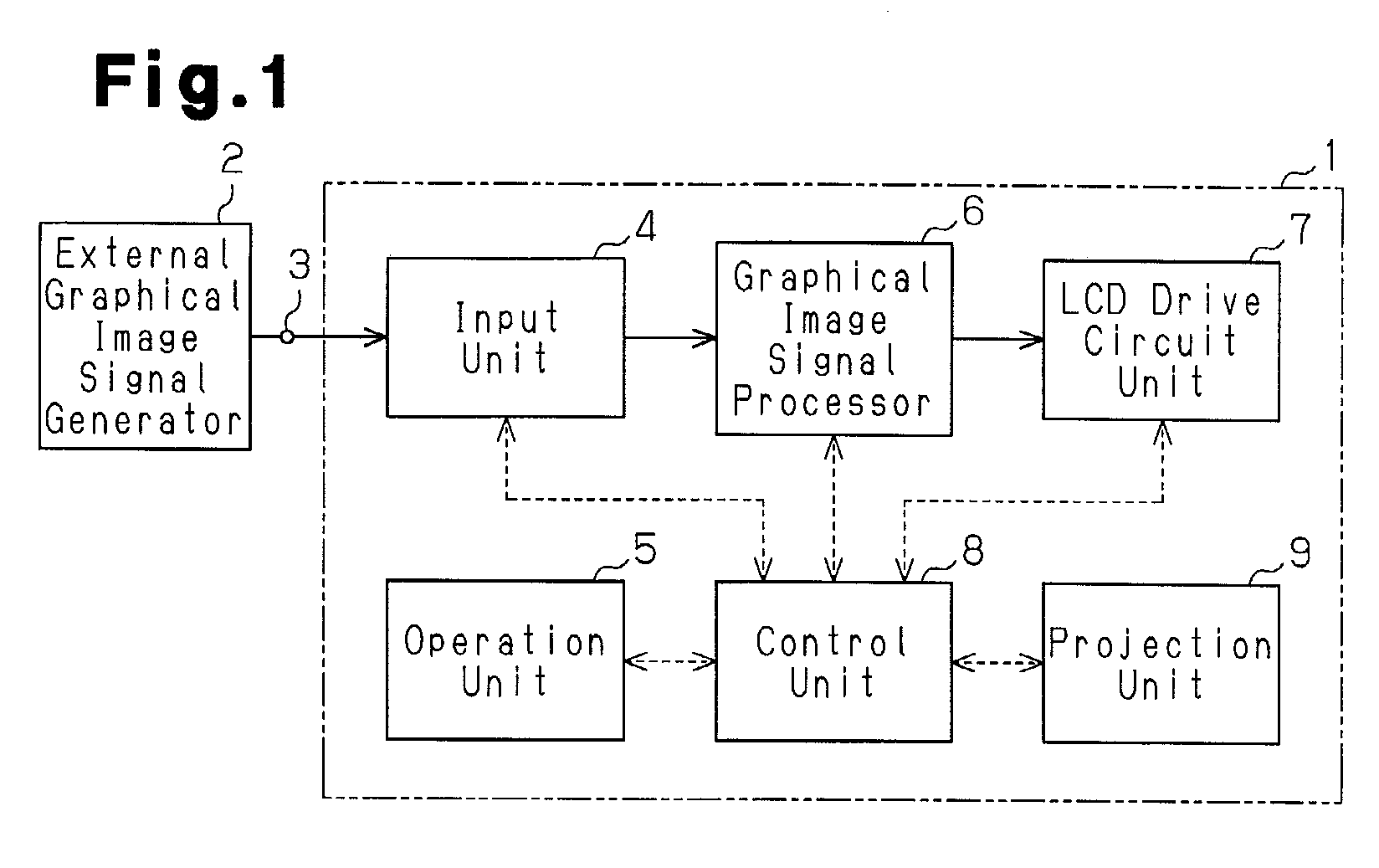
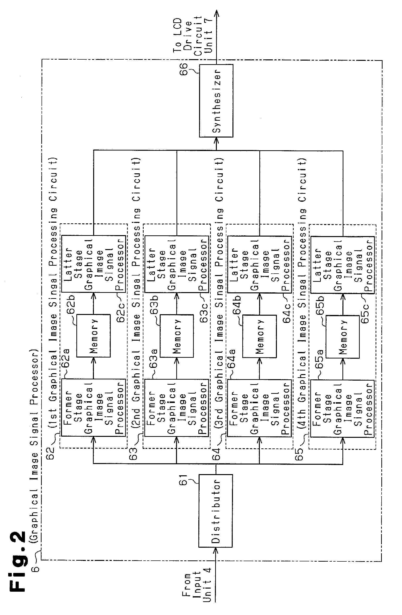
[0029]Referring to FIG. 1, an LCD projector 1 includes an input connector 3, which receives graphical signal data from an external graphical signal generator 2. An input unit 4 receives the graphical signal data via the input connector 3 and performs input processing on the graphical signal data. An operation unit 5 is used to select a projection mode for the LCD projector 1. A graphical signal processor 6 performs graph...

second embodiment

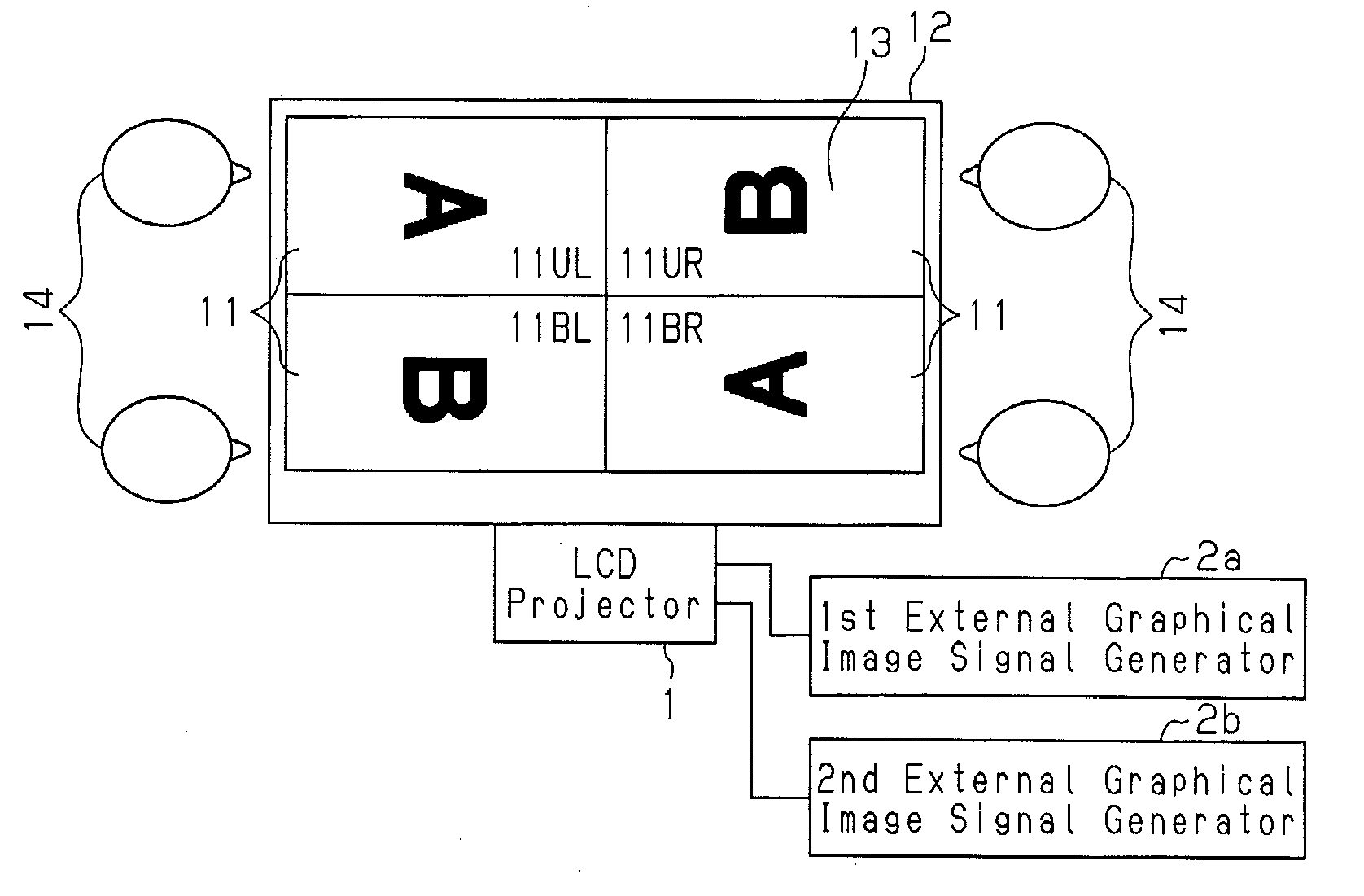
[0048]FIG. 7 shows an example of a conference projector system, which uses the LCD projector 1 of the The LCD projector 1 projects a single projection frame 13 onto a conference table surface 12. A plurality of viewers 14 are situated near the projection frame 13. The projection frame 13, which includes four split screens 11, simultaneously displays two different graphical images (shown as characters “A” and “B”), which are generated from two different pieces of graphical signal data, in different orientations. More specifically, in the set of the upper left split screen 11UL and the lower left split screen 11BL, two different graphical images (shown as characters “A” and “B”) are displayed next to each other oriented in the same direction that is proper for the viewers at the left side of the projection frame 13. In the set of the upper right split screen 11UR and the lower right split screen 11BR, two different graphical images (shown as characters “A” and “B”) are displayed next...


PUM


Abstract

A projector that displays a projection frame includes an operation unit to select a projection mode designating the number of split screens in the projection frame and the location, size, and orientation of each split screen. An input unit processes graphical signal data provided from an external graphical signal generator to generate processed graphical signal data. A distributor distributes the processed graphical signal data to graphical signal processing circuits, each performing data conversion and adjustment in accordance with the projection mode on the distributed graphical signal data to generate adjusted graphical signal data for one of the split screens. A synthesizer combines the adjusted graphical signal data to generate combined graphical signal data. A projection unit projects the combined graphical signal data as a single projection frame.

Description

CROSS-REFERENCE TO RELATED APPLICATIONS[0001]This application is based upon and claims the benefit of priority from prior Japanese Patent Application No. 2008-084384, filed on Mar. 27, 2008, the entire contents of which are incorporated herein by reference.BACKGROUND OF THE INVENTION[0002]The present invention relates to a projector device that combines data from a plurality of graphical signals, each of which has undergone graphical signal processing, to form combined graphical signal data for projection as a single projection frame. The present invention also relates to a projector system using such a projector device.[0003]A graphic display device that projects a single projection frame including a plurality of split screens is known in the prior art. The plurality of split screens simultaneously display different graphical images. The graphic display device of the prior art receives data of a plurality of graphical signals, stores the data for each graphical signal in a memory, ...

Claims


Application Information

Patent Timeline
Patent Type & Authority Applications(United States)
IPC IPC(8): H04N5/445H04N9/31G09G3/20G09G5/00G09G5/14G09G5/36H04N5/74
CPCG03B21/26H04N9/3197H04N9/3185
Inventor ASANO, TAKEHIKOYAMAMOTO, KOKI
Owner SANYO ELECTRIC CO LTD
Why Eureka
Try Eureka