

Image display device
- Summary
- Abstract
- Description
- Claims
- Application Information
AI Technical Summary
Benefits of technology
Problems solved by technology
Method used
Image

Examples
Embodiment Construction
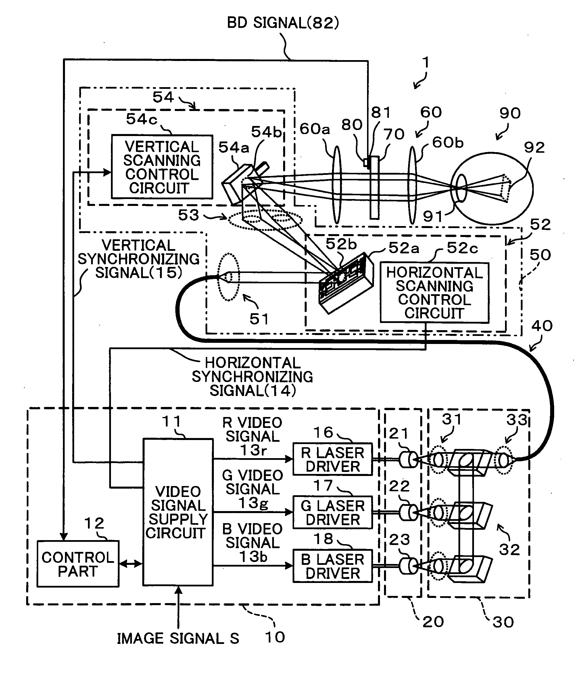
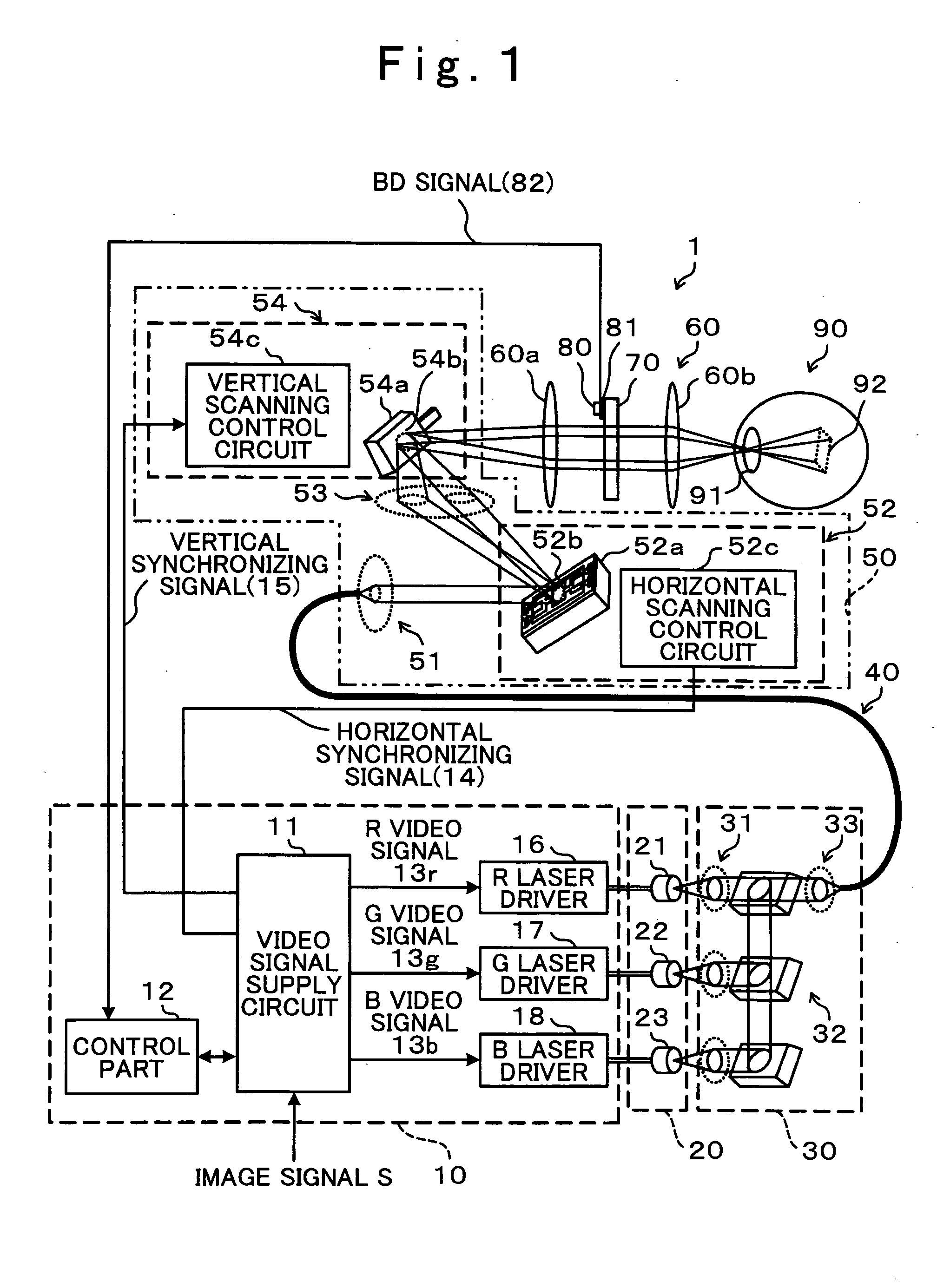
[0022]Hereinafter, an image display device of a preferred embodiment of the present invention is explained in conjunction with attached drawings. Hereinafter, the explanation will be made mainly with respect to a retinal-scanning-type image display device which includes a light source part having a light source which radiates light having intensity corresponding to a supplied electric current, and an optical scanning part which performs two-dimensional scanning of the light radiated from the light source, wherein an image is displayed on a retina by projecting an image forming light scanned by the optical scanning part to at least one of retinas of a viewer. However, the present invention is not limited to such a retinal-scanning-type image display device, and is also applicable to other image display devices. That is, for example, the present invention is applicable to an image projecting device which displays an image by projecting an image forming light obtained by scanning using...
PUM
 Abstract
Description
Claims
Application Information