Light emitting unit arrangement and control system and method thereof

a technology of light emitting units and control systems, applied in the direction of lighting and heating apparatus, process and machine control, instruments, etc., can solve the problems of reducing color and brightness accuracy, visible color differences, and background light not constant, and achieve stable light output

Active Publication Date: 2012-04-17
SIGNIFY HLDG BV
View PDF14 Cites 6 Cited by
  • Summary
  • Abstract
  • Description
  • Claims
  • Application Information

AI Technical Summary

Benefits of technology

[0008]It is an object of the present invention to at least partly overcome this problem, and to provide an improved control system, light emitting unit arrangement and control method, which in particular can cope with a non-constant environment to provide a stable light output in such an environment.
[0011]The switching period is generally the time frame in which the LEDs are energized or switched on / off for a certain time (on-time) in order to provide a certain output, and a random switching period means that it has a random duration or length. Hereto, the invention is based on the understanding that by randomizing the switching period, the LED(s) may be operated with a random switching frequency, and the likelihood of significantly reducing interference caused by a periodic fixed frequency external light source is high. Also, it may reduce interference to other nearby light sources.
[0013]The random period is preferably determined using an existing random number generator of the control unit, thereby not increasing hardware costs. Alternatively, pseudo random numbers or random number tables or the like could be used.
[0020]In one embodiment, feedback signal values above a predetermined value for each color away are during operation filtered away before comparison with the reference signal. A low pass filter may for instance be used for this purpose. In this way, any abnormally high measurement values of the feedback signal, which may be due to the fact that the sensor unit samples the color at the instant that an adjacent pulsed light source is on, are removed. This may further reduce any interference effects.
[0021]In another embodiment, feedback signal extreme values for each color for a certain interval are during operation removed before comparison with the reference signal. That is, the highest and lowest measurement values of the feedback signal detected during a certain interval are discarded, which measurement values may be the result of erroneous measurements. This may also reduce any interference effects, and may be effected during operation by the control unit suitably adapted thereto.

Problems solved by technology

For instance, when creating white light by mixing red, green and blue LEDs, the temperature effects will already result in a visible color difference after a small rise in temperature.
However, in some practical cases, the background light is not constant.
This non-constant interference would significantly affect the above model and reduce the color and brightness accuracy.
However, the space (i.e. the frame) within which the LED emission windows can be varied is limited, which means that a pulsed external light source with similar or lower frequency as the light emission unit still may cause interference.

Method used


Image

  • Light emitting unit arrangement and control system and method thereof
  • Light emitting unit arrangement and control system and method thereof
  • Light emitting unit arrangement and control system and method thereof

Examples


Embodiment Construction

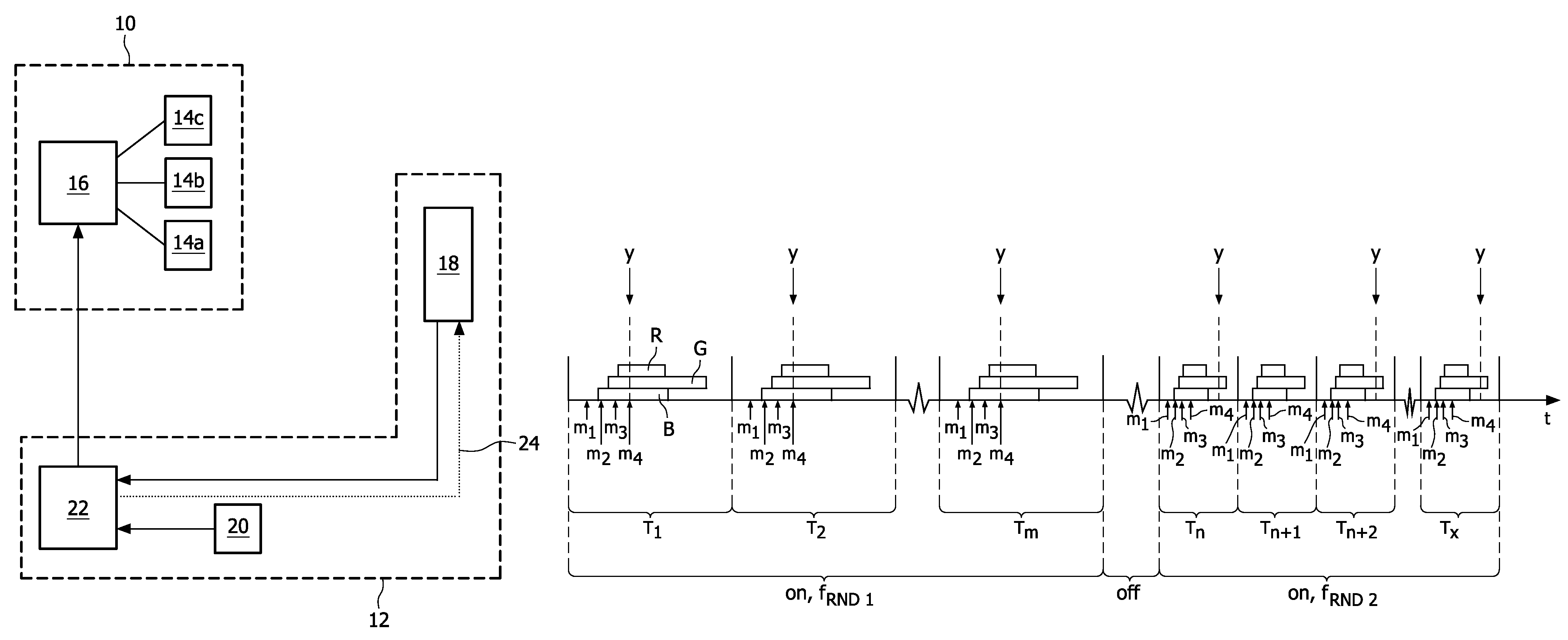
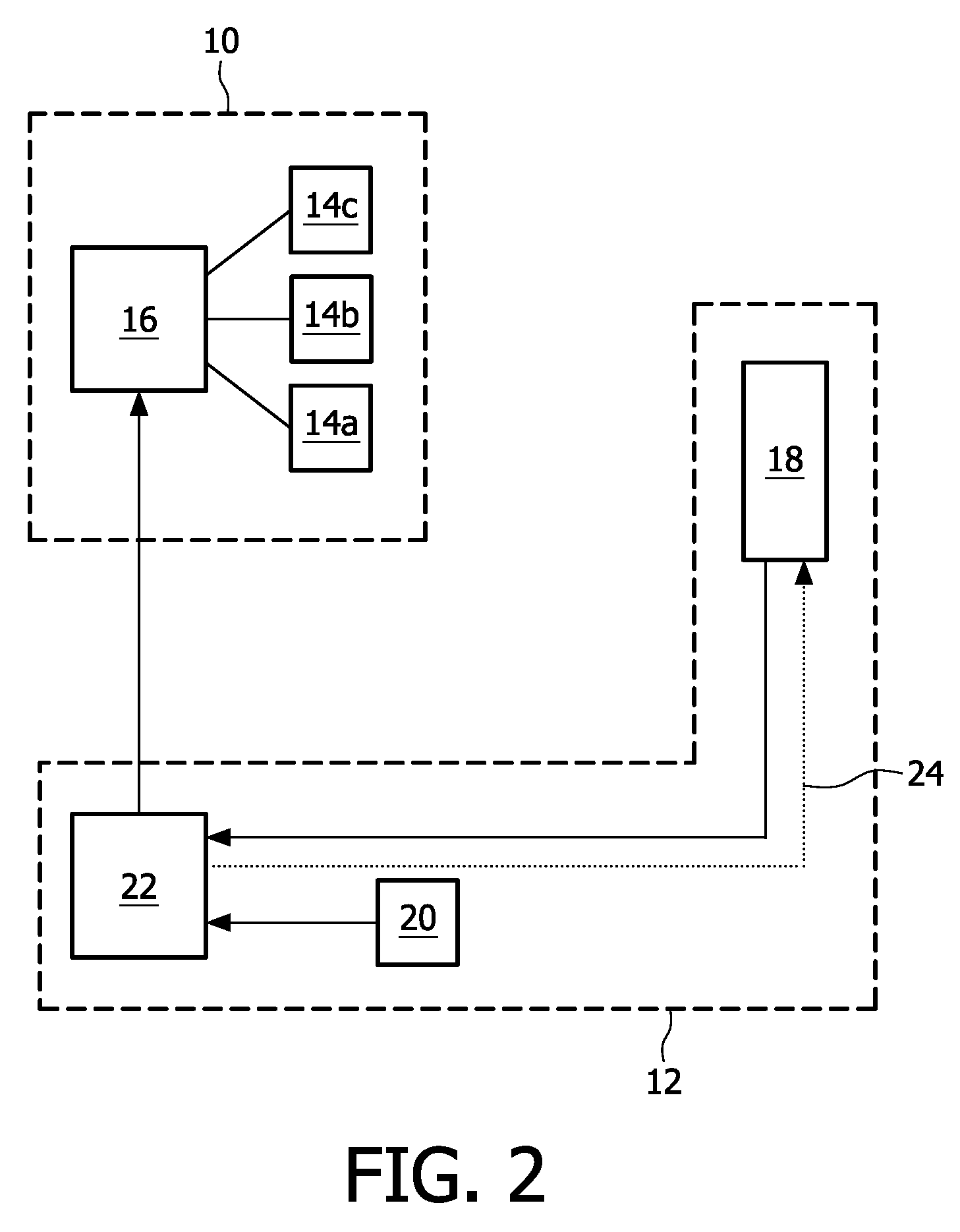
[0028]FIG. 2 is a schematic block diagram illustrating a light emitting unit 10 and a control system 12 in a light emitting unit arrangement according to an embodiment of the present invention. The light emitting unit 10 and the control system 12 may be mounted on a printed circuit board (PCB) or the like (not shown).

[0029]The light emitting unit 10 comprises an array of LEDs 14, for instance one or more LEDs 14a adapted to emit red light, one or more LEDs 14b adapted to emit green light, and one or more LEDs 14c adapted to emit blue light. The LEDs 14 are connected to a power supply unit 16 for lighting or energizing the LEDs 14.

[0030]The control system 12 comprises a sensor unit 18 generally adapted to detect the flux or intensity or radiative power of the light emitted from the LEDs 14 of the light emitting unit 10, and provide a feedback signal indicative of the current or present or instantaneous flux. The sensor unit 18 may comprise an optical sensor, such as a photo-diode, wh...


PUM


Abstract

The present invention relates to a control system (12) for controlling the light output of a light emitting unit (10), which light emitting unit comprises at least one light emitting diode (LED) (14) and is adapted to emit light of at least one color, the control system comprising: a sensor unit (18) adapted to detect the light output of the light emitting unit and provide a corresponding feedback signal; and a control unit (22) adapted to control the light output of the light emitting unit based on a comparison between the feedback signal and a corresponding reference signal representing a desired light output, in order to provide an improved light output, wherein the control unit is further adapted to: determine a random switching period; determine on-time(s) for the LED(s) within the random switching period for providing the improved light output; and control energizing of the LED(s) according to the determined period and on-time(s). The present invention also relates to an LED light emitting unit arrangement, and a method for controlling the light output of an LED light emitting unit.

Description

FIELD OF THE INVENTION[0001]The present invention relates to a system for controlling the light output of an LED light emitting unit, an LED light emitting unit arrangement, and a method for controlling the light output of an LED light emitting unit.BACKGROUND OF THE INVENTION[0002]Light from multiple colored LEDs (e.g. red, green, blue) of a light emitting unit may be mixed to obtain white or colored light.[0003]However, the output (e.g. emitted flux and spectral distribution) of the LEDs will vary due to for instance (differential) ageing and temperature influence, binning, etc. For instance, when creating white light by mixing red, green and blue LEDs, the temperature effects will already result in a visible color difference after a small rise in temperature.[0004]Hereto, a number of models for achieving a stable output (color) of such a light emitting unit have been proposed, for instance temperature feed forward (TFF), color coordinates feedback (CCFB), flux feedback (FFB), or ...

Claims


Application Information

Patent Timeline
Patent Type & Authority Patents(United States)
IPC IPC(8): H05B37/02H05B44/00
CPCH05B33/0818H05B33/0869H05B33/0851Y02B20/346H05B45/22Y02B20/30H05B45/3725H05B45/12F21Y2115/10
Inventor DEURENBERG, PETER HUBERTUS FRANCISCUSNIEUWLANDS, ERIK
Owner SIGNIFY HLDG BV
Why Eureka
Try Eureka