LED lamp

A technology of light-emitting diodes and lamps, which is applied to semiconductor devices of light-emitting elements, light sources, electric light sources, etc. It can solve the problems of deviation in lighting direction, inapplicability, and inability to overcome the correct lighting direction of electric connection lamps, etc., and achieve good electrical connection.

Inactive Publication Date: 2011-04-06
FU ZHUN PRECISION IND SHENZHEN +1
View PDF5 Cites 7 Cited by
  • Summary
  • Abstract
  • Description
  • Claims
  • Application Information

AI Technical Summary

Problems solved by technology

However, since the above-mentioned screw-type lamp cap can only exert the characteristics of electrical connection when it is screwed tightly to the lamp holder, it will often deviate from the required lighting direction when screwed without controlling the lighting direction.
If you want to turn out the lamp head at an angle to achieve the lighting in a specific direction of the lamp, you may not be able to overcome the problem of electrical connection and easy looseness, which will cause the problem of not being able to maintain the correct lighting direction of the lamp for a long time. Therefore, no matter for existing lamps or LED lamps In other words, the existing lamp head is not suitable for lighting applications that need to emit light in a specific radial direction

Method used


Image

  • LED lamp
  • LED lamp
  • LED lamp

Examples


Embodiment Construction

[0021] Refer to the following Figure 1 to Figure 9 , to further illustrate the light-emitting diode lamp of the present invention.

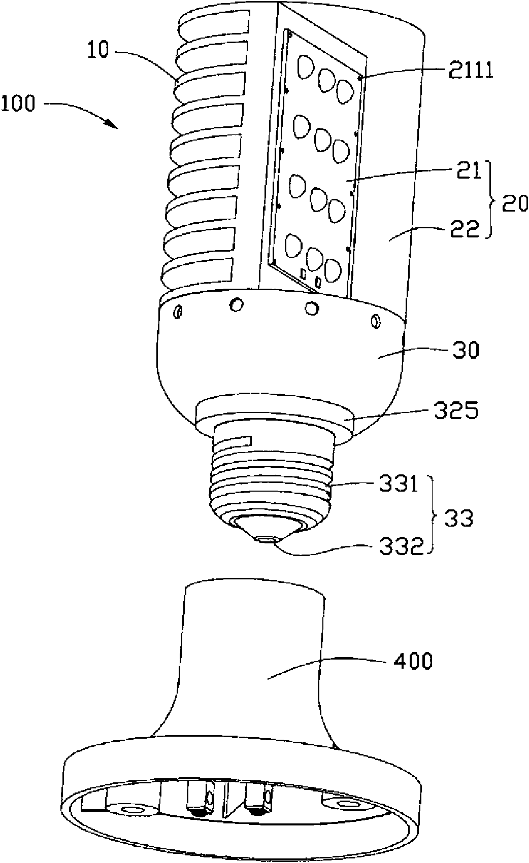
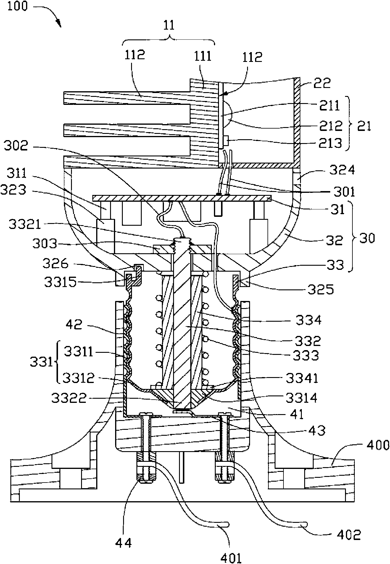
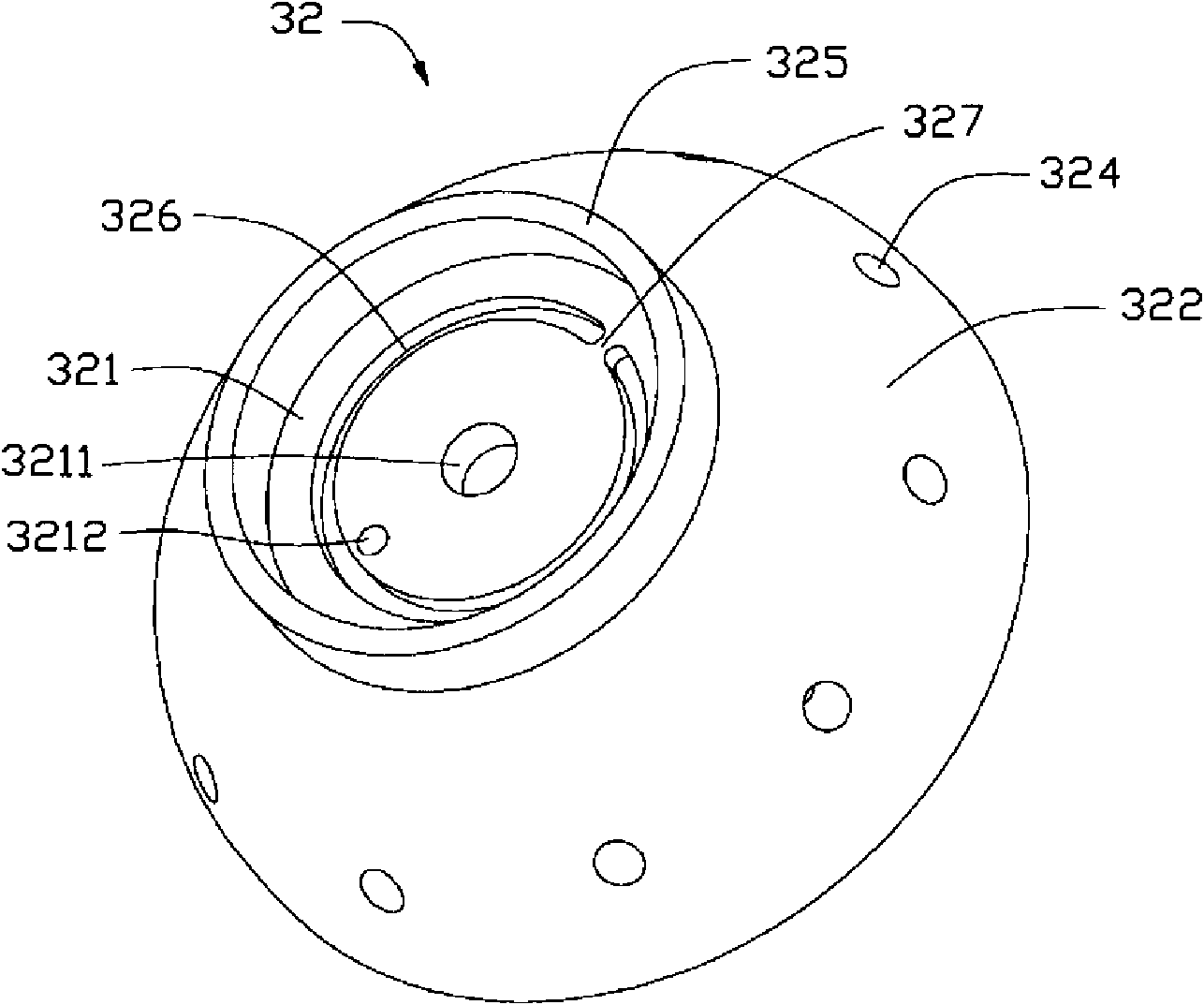
[0022] figure 1 It is a perspective view of the first embodiment of the light-emitting diode lamp 100 and a lamp holder 400 of the present invention, figure 2 Yes figure 1 The assembly cross-sectional view of the light-emitting diode lamp 100 and the lamp holder 400 shown, image 3 Yes figure 2 A perspective view of a housing 32 in the LED lamp 100 shown. The LED lamp 100 mainly includes a heat dissipation part 10 , an optical part 20 and an electrical part 30 .

[0023] The heat sink 10 includes a heat sink 11 made of metal with good thermal conductivity. The heat dissipation element 11 includes a heat dissipation base 111 and a plurality of fins 112 protruding along one side of the heat dissipation base 111. The heat dissipation base 111 is a plate extending longitudinally along the heat dissipation element 11. The heat dissipation bas...


PUM


Abstract

The invention discloses an LED (light emitting diode) lamp which comprises a radiating part, an optical part and an electric part. The radiating part is provided with a radiating piece; and the optical part comprises an LED light source arranged on the radiating piece and a light guide cover which covers the LED light source inside. The electric part comprises a shell, a circuit board arranged in the shell and a lamp holder. The shell comprises a bottom plate and an annular side wall extending toward the radiating part and the optical part from the periphery of the bottom plate, and is connected with the radiating part and the optical part through the side wall. The lamp holder is arranged at the outer end of the bottom plate of the shell and comprises a conductive sleeve and a conductive column axially inserted into the conductive sleeve. The lamp holder is pivoted with the shell through the conductive column. Mutually-cooperating direction adjusting structures are arranged between the lamp holder and the shell so as to adjust the light emission direction of the LED lamp.

Description

technical field [0001] The invention relates to a light-emitting diode lamp, in particular to a light-emitting diode lamp with adjustable lighting direction. Background technique [0002] The energy consumed by existing lighting fixtures is extremely considerable. The development of lighting energy saving is an important new energy technology. Semiconductor lighting uses high-brightness light-emitting diodes (LEDs) as light sources. This new light source is characterized by its high luminous efficiency, energy saving, longevity, and environmental protection. (No mercury, toxic gas), quick start, directivity, shock resistance and impact resistance, etc., have the potential to widely replace traditional lighting sources. [0003] When using LEDs as new light sources for lighting, it is necessary to cooperate with a high-efficiency heat dissipation mechanism to minimize the junction temperature of the LEDs (Junction temperature) in order to take advantage of the above-mentioned...

Claims


Application Information

Patent Timeline
Patent Type & Authority Applications(China)
IPC IPC(8): F21S2/00F21V29/00F21V15/02F21V23/00F21V19/02F21Y101/02
CPCF21V29/225F21K9/00F21S6/002F21Y2101/02F21Y2103/003F21V29/004F21V29/507F21V29/763F21V29/83F21K9/23F21K9/65F21Y2103/10F21Y2115/10F21K9/238F21K9/235
Inventor 刘泰健
Owner FU ZHUN PRECISION IND SHENZHEN
Why Eureka
Try Eureka