Main unit structure of digital control laser cutting machine tool

A CNC laser and cutting machine technology, applied in laser welding equipment, metal processing machinery parts, large fixed members, etc., can solve problems such as poor transmission rigidity, reduced cutting accuracy, asynchronous distortion of gantry beams, etc., to enhance stability and Strength, improve cutting accuracy, reduce the effect of the overall inertia

Inactive Publication Date: 2008-11-12
JIANGSU JINFANGYUAN CNC MACHINE CO LTD
View PDF0 Cites 7 Cited by
  • Summary
  • Abstract
  • Description
  • Claims
  • Application Information

AI Technical Summary

Problems solved by technology

Its disadvantages are: due to the heavy weight of the gantry beam, it affects the improvement of the movement speed; there is an asynchronous problem in the drive of the rack and pinion mechanisms on both sides, which will cause asynchronous distortion of the gantry beam and reduce the cutting accuracy. poor proximity
The disadvantages of this structure are: since one end of the cantilever beam is suppo

Method used


Image

  • Main unit structure of digital control laser cutting machine tool
  • Main unit structure of digital control laser cutting machine tool

Examples


Embodiment Construction

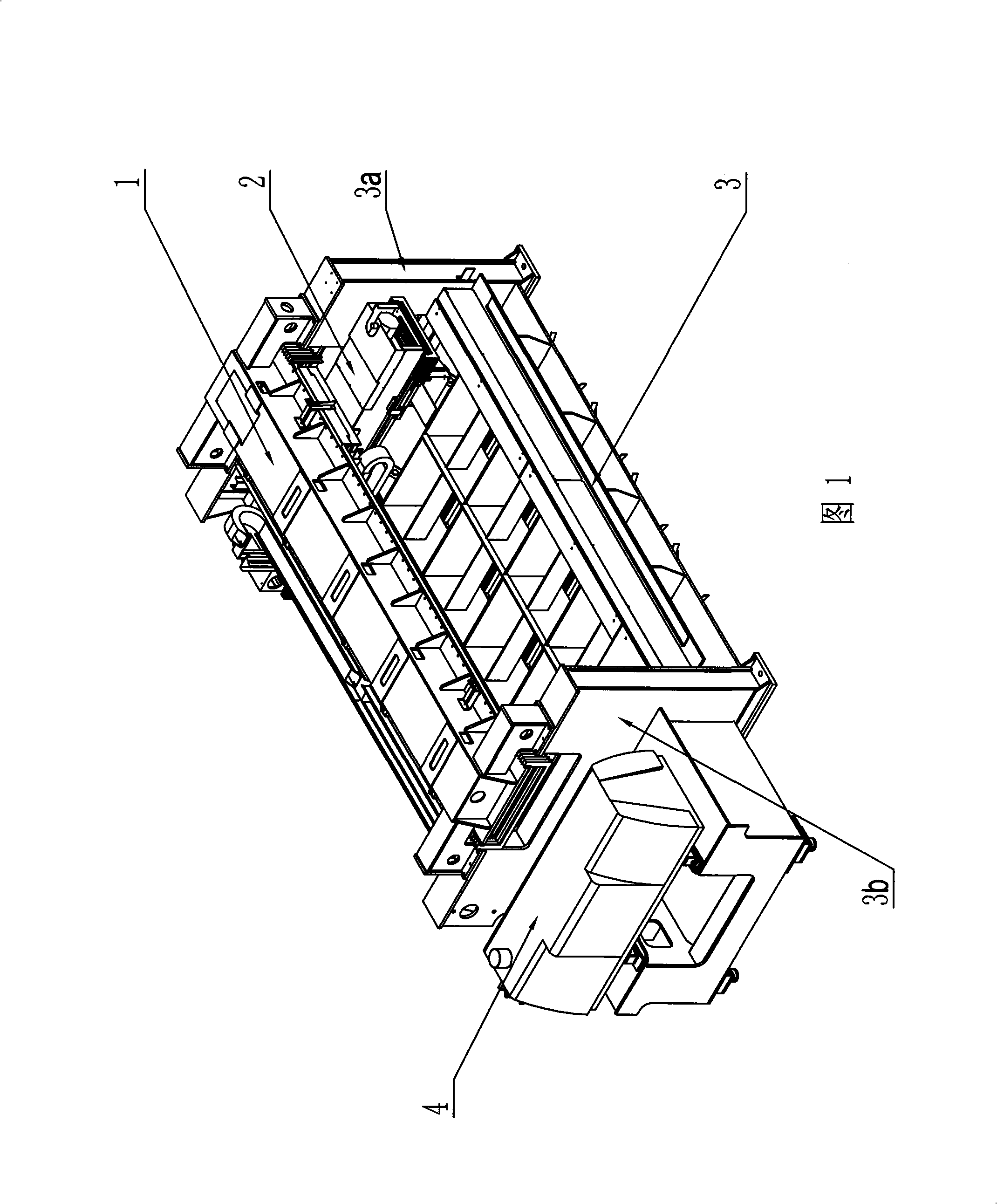
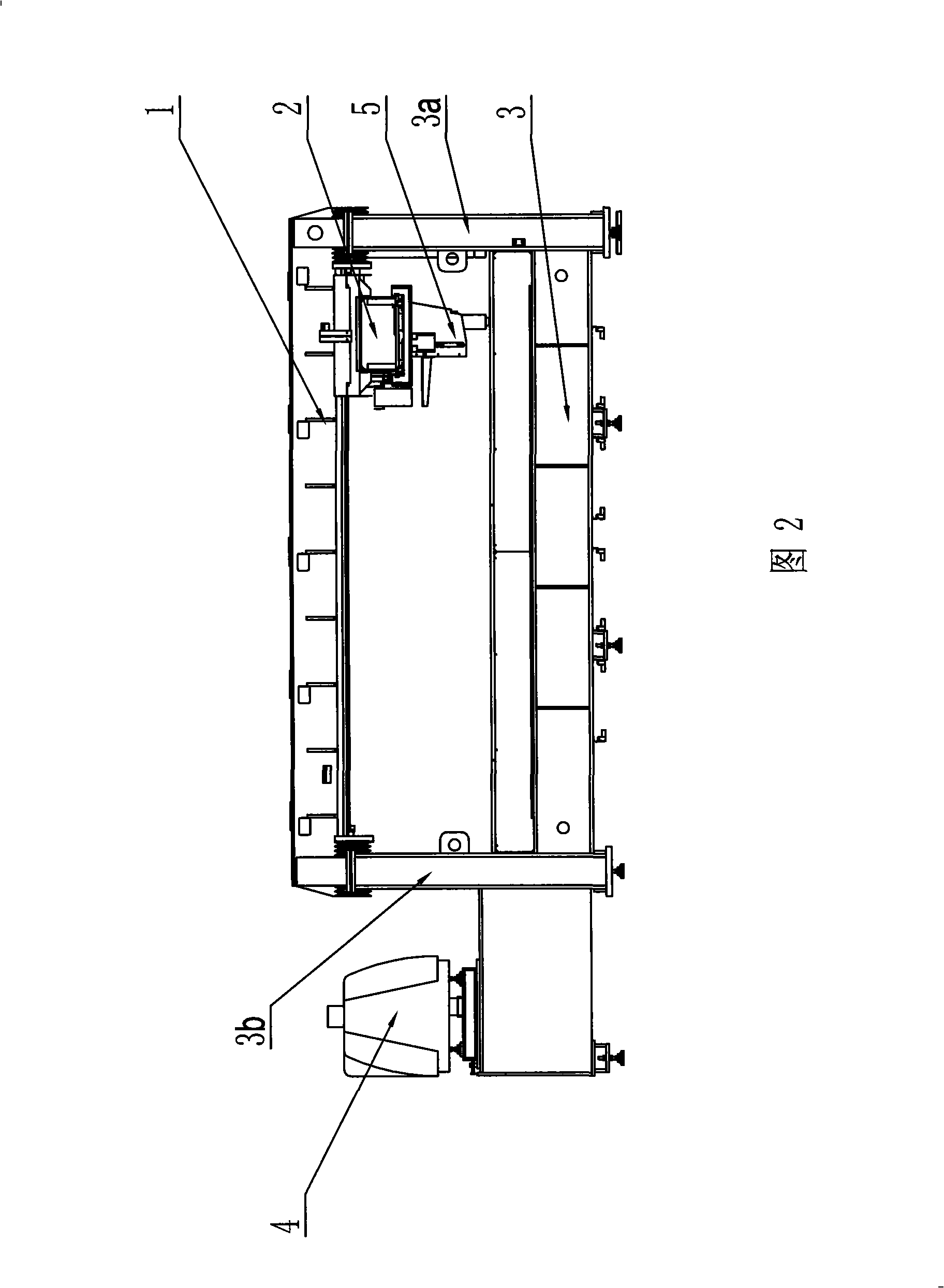
[0014] As shown in Figure 1-2, it is the host structure of the CNC laser cutting machine, including the fuselage 3, the laser 4, the gantry beam 1 and the cutting head 5. It is composed of a plurality of integral steel plates welded, the support frames 3a, 3b are part of the fuselage, and the gantry beam is arranged between the upper sides of the support frames 3a, 3b; the laser 4 is fixedly installed on the support frame 3b at one end, when the laser 4 emits laser light , the laser beam is transmitted to the cutting head 5 to realize cutting. The two ends of the gantry beam 1 are respectively fixedly connected with the corresponding support frames 3a and 3b. 2 and the gantry beam 1 are vertically arranged in space, and the lower side of the moving beam 2 is suspended with a cutting head 5 that can move along the length direction of the moving beam.

[0015] This device fixedly connects the gantry beam 1 with the support frame 3a, 3b, so that the fuselage 3 forms a stable annu...


PUM


Abstract

The invention discloses a host machine structure of a numerical control cutting machine in the field of laser cutting machines, comprising a machine body, a laser, a gantry beam, a movable crossbeam and a cutting head; the front side and the rear side of the machine body are provided with a supporting frame which is vertically arranged; the gantry beam is arranged between the upper sides of two supporting frames; when the laser emits the laser, the laser is transmitted to the cutting head; two ends of the gantry beam are fixedly connected with corresponding supporting frames respectively; the movable crossbeam which can move along the length direction of the gantry beam is suspended at the lower side of the gantry beam; the movable crossbeam and the gantry beam are vertically arranged in space; the cutting head which can move along the length direction of the movable crossbeam is suspended at the lower side of the movable crossbeam. The device leads the gantry beam to be fixedly connected with the supporting frame, reinforces the strength of the machine tool, and improves the stability of the machine tool; the middle driving of the movable crossbeam effectively reduces the vibration, leads the cutting head to realize the high-speed movement, and improves the cutting speed. The host machine structure can be used for the cutting of numerical control laser.

Description

technical field [0001] The invention relates to a numerically controlled laser cutting machine, in particular to a host structure of the numerically controlled laser cutting machine. Background technique [0002] CNC laser cutting machine uses laser as a processing method to process parts of metal and non-metal plates. The CNC system controls the X-axis and Y-axis servo motors to drive the cutting head to realize the compound motion of the plane, which can be processed on the plane plate. Straight lines and curves of any shape. This equipment is a highly efficient and highly automated plate cutting equipment, which is widely used in textile machinery, machinery manufacturing, automobiles, instrument switches, home appliance manufacturing, elevator equipment manufacturing, food industry, decoration and advertising, etc. [0003] At present, there are two main structures of CNC laser cutting machines: [0004] A double-sided driving gantry beam mobile structure, including th...

Claims


Application Information

Patent Timeline
IPC IPC(8): B23Q1/01B23K26/38
Inventor 何承义周庆岳俊强刘爱伟
Owner JIANGSU JINFANGYUAN CNC MACHINE CO LTD
Why Eureka
Try Eureka