Method of driving MEMS mirror scanner, method of driving MEMS actuator scanner and method of controlling rotation angle of MEMS actuator

a technology of mirror scanner and actuator, applied in the field of microelectromechanical systems, can solve the problems of unintended mirror angle response, unattainable time-angle response feature required by each specific application, loss of part of the advantages of using a mems mirror scanner, etc., to achieve the desired time-angle response feature, ensure the degree of freedom in driving, and quickly determine parameters

Inactive Publication Date: 2009-10-01
KK TOPCON
View PDF5 Cites 65 Cited by
  • Summary
  • Abstract
  • Description
  • Claims
  • Application Information

AI Technical Summary

Benefits of technology

[0023]It is, therefore, an object of the present invention to provide a method of driving a MEMS mirror scanner and a MEMS actuator scanner and controlling a rotation angle of a MEMS actuator, which accurately damp their oscillation to a resting state, and simplify a scheme of driving without using a large capacity memory, so as to quickly determine parameters and sufficiently ensure the degree of freedom in driving.

Problems solved by technology

However, such driving requires a time long enough to be able to ignore effects of the inertia and damping, and a part of the advantages in using a MEMS mirror scanner is lost.
On the other hand, if driving time is simply reduced, an unintended mirror angle response results from effects of the inertia and damping, which are dynamic features.
Although the oscillation of a MEMS mirror scanner can be suppressed to some degree by the techniques disclosed in the above documents 1-6, a desired time-angle response feature required by each specific application can not be achieved.
In the methods illustrated in FIG. 3, a parameter reference table is required, but this reference table includes a large amount of data which requires a large capacity of memory and complicates a driving scheme.
Moreover, it takes a long time to experimentally determine the parameters.
Furthermore, although in the case of the driving waveform illustrated in FIG. 3, the driving waveform has a simple shape, which seems to be easily generated, error tolerance of the waveform for controlling the transient oscillation (ringing) becomes extremely stringent.

Method used


Image

  • Method of driving MEMS mirror scanner, method of driving MEMS actuator scanner and method of controlling rotation angle of MEMS actuator
  • Method of driving MEMS mirror scanner, method of driving MEMS actuator scanner and method of controlling rotation angle of MEMS actuator
  • Method of driving MEMS mirror scanner, method of driving MEMS actuator scanner and method of controlling rotation angle of MEMS actuator

Examples


embodiment

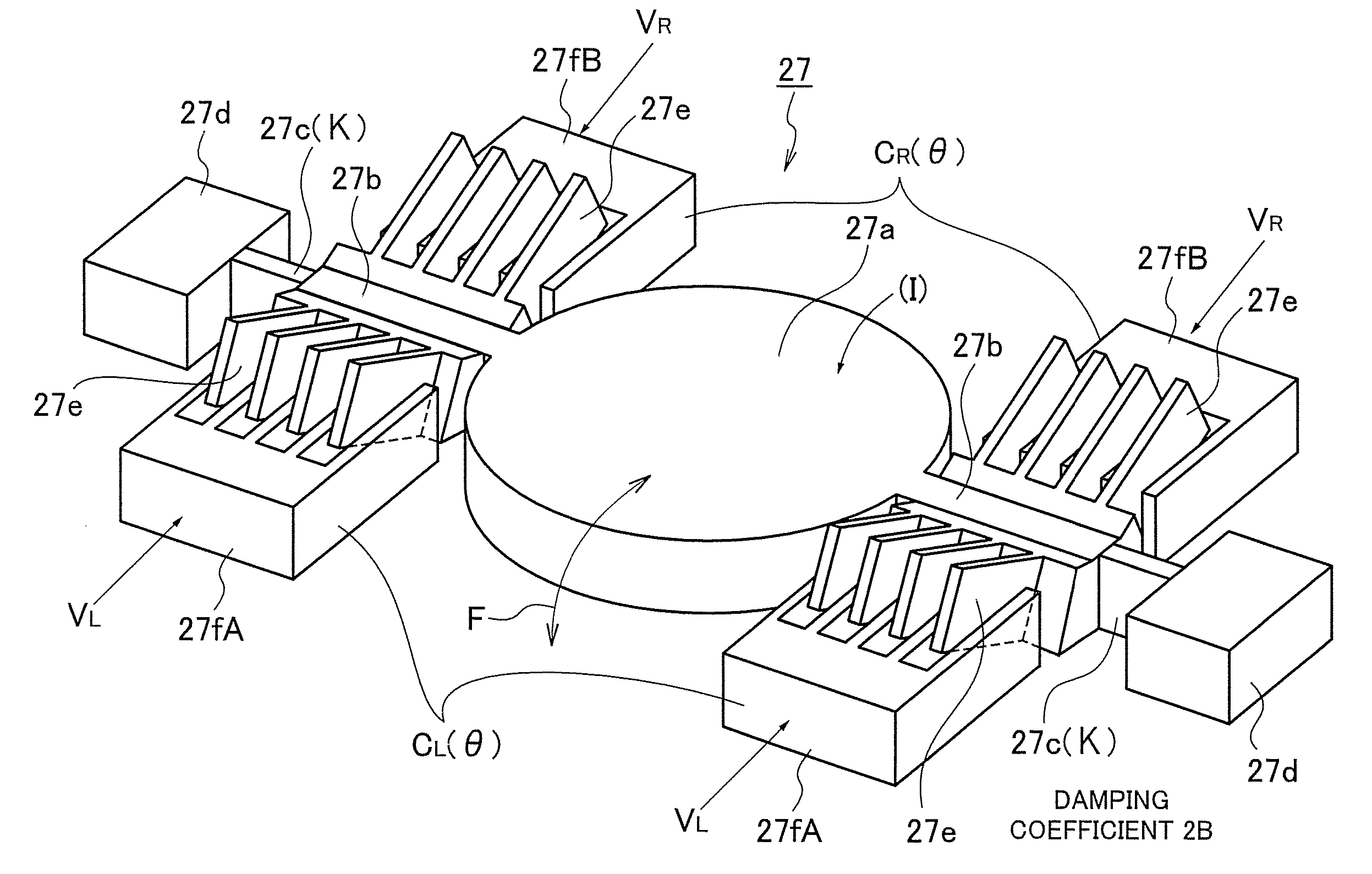
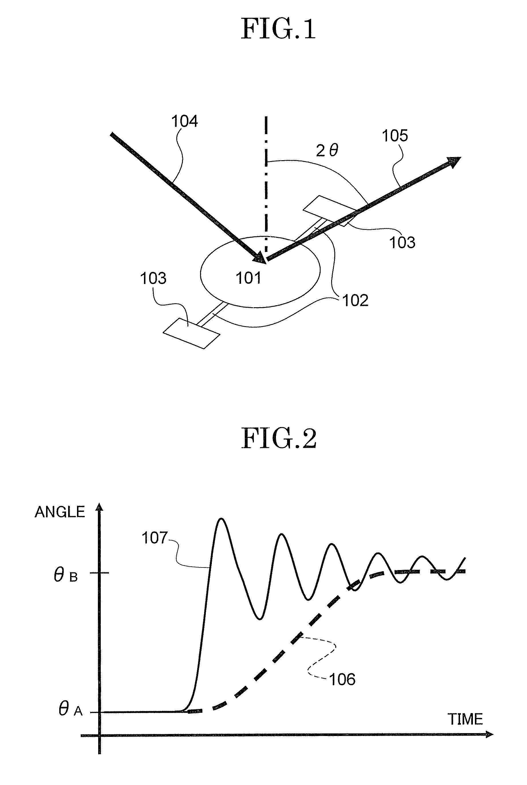
[0065]Generally, in the case of the MEMS mirror scanner illustrated in FIG. 1, the equation of motion with respect to the rotation angle θ of a mirror 101 is expressed by the following equation, where I is a moment of inertia of the rotating part including the mirror 101, 2B is a damping factor, κ is a spring constant, and TL and TR are driving torques of the right and left actuators, respectively.

I{umlaut over (θ)}+2B{dot over (θ)}+κθ=TTotal(θ,w)   (1)

where {umlaut over (θ)}=d2θ / dt2, {dot over (θ)}=dθ / dt

[0066]In this case, the coefficients of the rotation angle, the first order derivative of the rotation angle with respect to time and the second order derivative of the rotation angle with respect to time are denominated an elastic term, a damping term and an inertia term, respectively. When the motion of an actuator is not angular but translational, the coefficients of the displacement, the first order derivative of the displacement with respect to time and the second order deriva...


PUM


Abstract

A method of driving a MEMS mirror scanner having an electrostatic actuator, comprising a step of driving the electrostatic actuator according to an input signal in accordance with a driving waveform obtained by the following equation,
whenC+(θ)0VV(t)=1C+(θ)I[-C-(θ)IVB+-(1ICL(θ)θ)(1ICR(θ)θ)VB2+C+(θ)I(θ¨+2BIθ.+κIθ)]whenC+(θ)=0VV(t)=θ¨+2BIθ.+κIθ2C-(θ)IVB
    • where, B/I, κ/I, (1/I)·dCL(θ)/dθ and (1/I)·dCR(θ)/dθ are parameters for obtaining the driving waveform, θ(t) is a desired mirror angle response, I is a moment of inertia of a moving part including a mirror, 2B is a damping factor (damping coefficient), κ is a spring constant, CL(θ) and CR(θ) are angle dependencies of an electric capacitance, VB is a constant bias voltage in differential driving, and C+′(θ) and C′(θ) are ½ of the sum and the difference of the first order derivative of CL(θ) and CR(θ) with respect to θ, respectively, which are represented by defined equations.

Description

PRIORITY CLAIM[0001]The present application is based on and claims priorities from Japanese Patent Application No. 2008-094587, filed on Apr. 1, 2008, and Japanese Patent Application No. 2008-326960, filed on Dec. 24, 2008, the disclosures of which are hereby incorporated by reference in their entirety.BACKGROUND OF THE INVENTION[0002]1. Field of the Invention[0003]The present invention relates to micro-electro-mechanical systems (MEMS), in particular, to a method of driving a MEMS mirror scanner, a method of driving a MEMS actuator scanner, and a method of controlling a rotation angle of a MEMS actuator, a MEMS micro-scanner for use, for example, in an optical deflector for obtaining and displaying an image, reducing a sensing error by diffusion of light, and sensing by scanning light, and a method of controlling such a MEMS micro-scanner.[0004]2. Description of the Related Art[0005]Recently, with an increase in a speed and functions of optical devices, high-speed switching of an o...

Claims


Application Information

Patent Timeline
Patent Type & Authority Applications(United States)
IPC IPC(8): G02B26/10
CPCG02B26/105G02B26/0841
Inventor FUJINO, MAKOTOGOTO, YOSHIAKINAKANISHI, MICHIKOMARUYAMA, HIROTAKEKOBAYASHI, AKIOTAMURA, HIROKAZU
Owner KK TOPCON
Why Eureka
Try Eureka